Installation
Charton is built with a modular, pay-for-what-you-use architecture. By leveraging Cargo features, you can finely tune your compilation to match your production constraints—whether you are deploying to a resource-constrained WebAssembly environment, building high-throughput multi-threaded backends, or bridging to existing Python data science pipelines.
Adding Charton to Your Project
To get started with the standard, single-threaded configuration, add Charton to your Cargo.toml:
[dependencies]
charton = "0.8"
Tailoring with Cargo Features
For production deployments, we strongly recommend enabling specific features to unlock advanced performance and backend rendering capabilities:
[dependencies]
# Example 1: Enable multi-threaded data processing for massive Polars DataFrames
charton = { version = "0.8", features = ["parallel"] }

# Example 2: Enable native image and document encoders for direct file exports
charton = { version = "0.8", features = ["png", "pdf"] }
Feature Flag Matrix
| Feature Flag | Core Mechanism & Dependencies | Target Use Case |
|---|---|---|
parallel | Activates Rayon-backed parallel computation for scale arbitration and geometry derivation. | Processing high-density data, such as financial market depth charts or massive scatter plots. |
png | Pulls in native PNG encoding backends, activating the .save("out.png") API. | Automated server-side report generation and automated dashboard asset caching. |
pdf | Integrates a vector PDF document renderer, activating the .save("out.pdf") API. | Generating publication-quality vector figures compliant with top-tier scientific journals (e.g., NEJM). |
Quick Start
Charton’s API design mirrors the declarative philosophy of the Grammar of Graphics. To balance rapid prototyping flexibility with production-grade engineering rigor, Charton offers a dual-API paradigm: a fluid, concise chart! macro syntax and a deterministic, explicitly managed Chart::build Builder API.
Swift Prototyping with Macros
For data exploration, standalone scripts, or interactive notebook environments, the chart! macro offers an elegant, one-liner fluid interface to bind and map raw vectors instantaneously.
use charton::prelude::*;

fn main() -> Result<(), Box<dyn std::error::Error>> {
    // 1. Prepare raw observation vectors (Physical measurements: Height vs. Weight)
    let height = vec![160.0, 165.0, 170.0, 175.0, 180.0];
    let weight = vec![55.0, 62.0, 68.0, 75.0, 82.0];

    // 2. Linear declarative pipeline: bind -> instantiate mark -> map encoding -> save
    chart!(height, weight)?
        .mark_point()?
        .encode((alt::x("height"), alt::y("weight")))?
        .save("out.svg")?;

    Ok(())
}
Production-Grade Builder API
While the macro interface is exceptional for quick iterations, enterprise applications demand explicit control over data structures and memory boundaries. The Chart::build API decouples data layout from visual marks, ensuring absolute type safety and allowing for dynamic dataset mutation.
use charton::prelude::*;

fn main() -> Result<(), Box<dyn std::error::Error>> {
    let height = vec![160.0, 165.0, 170.0, 175.0, 180.0];
    let weight = vec![55.0, 62.0, 68.0, 75.0, 82.0];

    // 1. Explicitly manage the lifecycle of your Dataset
    let mut ds = Dataset::new()
        .with_column("height", height)?
        .with_column("weight", weight)?;

    // Note: If you need to append data dynamically within conditional branches or loops,
    // utilize the `add_column` method instead:
    // ds.add_column("age", vec![20, 22, 25, 30, 35])?;

    // 2. Build the chart deterministically via a strongly-typed constructor pipeline
    Chart::build(ds)?
        .mark_point()?
        .encode((alt::x("height"), alt::y("weight")))?
        .save("production_out.svg")?;

    Ok(())
}
High-Performance Polars Integration
Charton provides native, high-efficiency ingestion interfaces for Polars DataFrames. To shield your codebase from Polars’ rapid API evolution, Charton ships with versioned compilation macros to maintain bulletproof backwards compatibility.
use polars::prelude::*;
use charton::prelude::*;

fn main() -> Result<(), Box<dyn std::error::Error>> {
    // 1. Instantiate a standard Polars DataFrame
    let df = df![
        "height" => vec![160.0, 165.0, 170.0, 175.0, 180.0],
        "weight" => vec![55.0, 62.0, 68.0, 75.0, 82.0]
    ]?;

    // 2. Convert the DataFrame into a Charton Dataset (one-pass, columnar copy)
    // using the optimized version-specific macro
    let ds = load_polars_df!(df)?;

    // 3. Bind to the production Builder API
    Chart::build(ds)?
        .mark_point()?
        .encode((alt::x("height"), alt::y("weight")))?
        .save("polars_chart.svg")?;

    Ok(())
}
⚠️ Polars Version Compatibility Reference:
- Polars 0.53+: Use the modern standard macro
load_polars_df!(df)?. - Polars 0.44 - 0.52: Use the legacy support macro
load_polars_v44_52!(df)?. - Polars < 0.44: Unsupported. Upgrading your upstream Polars dependency is highly recommended.
Interactive Notebooks
In modern data engineering and scientific exploration, immediate feedback loops are essential. Charton natively implements runtime hooks for the Rust Jupyter kernel (evcxr_jupyter). By replacing disk-bound .save() sequences with the specialized .show() terminal API, you can render high-fidelity, inline SVG vector visuals instantly within individual notebook cells.
Prerequisites
Before initiating plotting routines inside a notebook, ensure the underlying EVCXR kernel is initialized globally within your local system architecture. See the Jupyter/evcxr article.
Notebook Inline Execution Blueprint
Create a fresh cell inside your Jupyter Notebook using the Rust (evcxr) kernel, and input the following configuration:
#![allow(unused)]
fn main() {
:dep charton = { version = "0.8" }
:dep polars = { version = "0.53", features = ["lazy"] }

use charton::prelude::*;
use polars::prelude::*;

// 1. Initialize evaluation dataframe
let df = df!["x" => [1, 2, 3], "y" => [10, 20, 30]].unwrap();
let ds = load_polars_df!(df).unwrap();

// 2. Compose the declarative graph layer
let chart = Chart::build(ds).unwrap()
    .mark_point().unwrap()
    .encode((alt::x("x"), alt::y("y"))).unwrap();

// 3. Execute inline visualization: renders high-fidelity vector graphics right into the notebook cell
chart.show().unwrap();
}
Deep Dive: Seamless Environment Self-Adaptation
The .show() method can seamlessly adapt its output behavior whether it is executed inside a live, interactive Jupyter workspace or run within a traditional console application. This resilience is achieved via Charton’s internal runtime environment probing mechanism.
Take a look at how .show() is engineered under the hood:
#![allow(unused)]
fn main() {
pub fn show(&self) -> Result<(), ChartonError> {
    // 1. Core Execution: Serialize the in-memory chart nodes and abstract layers into an SVG string
    let svg_content = self.to_svg()?;

    // 2. Probing Environment: Query the active process context for the EVCXR runtime signature
    if std::env::var("EVCXR_IS_RUNTIME").is_ok() {
        // 3. Protocol Handshake: When explicitly run within a Jupyter container,
        // intercept standard output and stream the tailored HTML payload wrapper
        println!(
            "EVCXR_BEGIN_CONTENT text/html\n{}\nEVCXR_END_CONTENT",
            svg_content
        );
    }

    // 4. Fallback Boundary Safety: If triggered within a regular CLI, microservice,
    // or CI/CD test harness, this method safely concludes with an Ok(()) without
    // polluting standard error or panicking.
    Ok(())
}
}
The Charton Mental Model
This chapter introduces the design philosophy of Charton. Understanding the "Mental Model" is more important than memorizing APIs, as it governs how you structure data and compose complex, production-grade visualizations in Rust.
The Declarative Paradigm: "What, Not How"
Charton is built on the Grammar of Graphics. In traditional imperative plotting libraries, you manually calculate coordinates and "draw" shapes on a canvas. In Charton, you provide a Specification that describes the relationship between data and visual properties.
#![allow(unused)]
fn main() {
Chart::build(&df)?
    .mark_point()           // Geometric Mark: Point
    .encode((
        x("weight"),        // Position Encoding: Map "weight" to X-axis
        y("horsepower"),    // Position Encoding: Map "horsepower" to Y-axis
        color("origin"),    // Visual Encoding: Map "origin" to Color
    ))?
}
The Layer Pipeline
Every layer answers four questions, in order:
- stat — what do the data mean? (density, binning, quartiles)
- position — where does each mark go? (identity, side by side)
- geometry — what shape is drawn? (point, bar, polygon)
- scale + coordinate — how does a value become a pixel?
Keeping the four apart is what lets a handful of basic parts describe almost any
chart. A violin plot, for example, is a density statistic, a position and a
polygon; the convenience mark mark_violin is just a name for that composition,
not a separate implementation. See
The Layer Pipeline for the full model.
The Orchestrator: LayeredChart
The LayeredChart is the central orchestrator of the system. It is not just a container; it is a State Machine that manages the visualization lifecycle through three key roles:
- Structural Intent: It holds multiple
Layerobjects. You can overlay a scatter plot, a regression line, and annotation text, ensuring they all exist within a shared logical space. - Stateful Overrides: It stores user-defined overrides for domains, ranges, and layouts. These explicit instructions take precedence over the default
Theme. - Physical Awareness: It bridges the gap between abstract math and pixels by managing canvas dimensions and coordinate transformations.
Scale Arbitration & Global Aesthetics
A core challenge in multi-layer charts is visual consistency. Charton solves this through Scale Arbitration:
- Unified Domains: Charton scans every layer to calculate a shared
ScaleDomain(the default, fixed behaviour). A faceted chart can instead train a scale inside each panel withwith_strategy("free"). Statistics are computed per panel, so a cumulative summary never mixes data across panels. - Aesthetic Consistency: The system maintains a unified visual language. If multiple layers map the "origin" column to
Color, Charton ensures they share the exact same palette and legend, preventing conflicting visual cues.
Space and Layout: From Logic to Physical
Charton treats space as a first-class citizen, separating the "logic" of a chart from its "physical" appearance:
- Coordinate Systems: Charton supports
CartesianandPolarsystems. The underlying mark logic remains identical; the coordinate system simply handles the transformation of normalized $[0, 1]$ values into canvas positions. - The Layout Engine: Charton uses a greedy stacking algorithm (similar to Flexbox). It automatically calculates the space required for titles, axis labels, and legends, ensuring the "Plot Panel" is perfectly centered and legible.
Performance & Rust's Ownership Model
Charton is engineered for the Rust ecosystem, leveraging its unique strengths:
- Columnar, JSON-Free Ingestion: Data is converted from Polars/Arrow into contiguous typed buffers — no JSON serialization or row-object overhead. Values are copied once at the boundary; downstream sharing between layers is reference-counted via
Arc. - Thread-Safe Resolution: Resolved scales are stored in
Arc<RwLock<...>>. This allows the rendering backend to safely access scale metadata across multiple threads, enabling high-performance parallel rendering. - Versioned Polars Macros: To solve "dependency hell," the core engine does not depend on
polarsdirectly. Conversion happens through version-matched macros (load_polars_df!,load_polars_v44_52!), so Charton keeps working even if your project pins a different Polars release.
Summary: The Charton Workflow
- Data: Prepare your Polars DataFrame.
- Specification: Compose
LayersusingMarksandEncodings. - Arbitration:
LayeredChartresolves globalScales,Guides, andLayouts. - Rendering: The
RenderBackend(SVG/PNG/PDF) translates geometry into the final output.
The Layer Pipeline: Data → Stat → Position → Geom
Charton describes a chart as a stack of layers. Each layer answers four independent questions, in this order:
| Question | Stage | Lives in |
|---|---|---|
| What values are there? | stat | transform |
| Where does each mark go? | position | position |
| What shape is drawn? | geometry | mark + render |
| How does a value become a pixel? | scale + coordinate | scale, coordinate |
Keeping the four stages apart is the whole point of a grammar of graphics: a
handful of basic parts can then describe almost any chart. This chapter explains
each stage, using a violin plot — the composition density estimate + dodge + polygon — as the running example. The composite marks such as mark_violin are
convenient names for exactly that composition, not a separate implementation.
For the rules that decide what becomes a mark — the tiers, the statistic contract and the thin-recipe rule — see Design Rules: Marks, Tiers & Statistical Atoms.
1. Stat — summarise the data
A statistic turns raw rows into the numbers a geometry needs. Examples:
- a histogram counts rows per bin;
- a box plot reduces each group to five numbers (min, q1, median, q3, max);
- a violin estimates the density of a numeric column.
Stats are ordinary transforms that run on the Dataset per group. A group is
the combination of the discrete aesthetics (colour, facet, and so on). In code:
#![allow(unused)]
fn main() {
chart!(iris)?
    .transform_density(                                              // stat
        DensityTransform::new("sepal_length")
            .with_as("sepal_length", "density")
            .with_trim(true))?
    .transform_band(BandTransform::new("sepal_length", "density"))?  // geometry
    .mark_polygon()?                                                 // mark
    .encode((alt::x("x"), alt::y("y"), alt::path_group("path_group")))?
}
transform_density writes the curve (sepal_length, density); the general
band geometry then turns it into x, y and a path_group id per violin.
Neither step knows or cares that a polygon will be drawn; each only produces a
table.
2. Position — decide where marks sit
When several marks share one category, they must be arranged. In a violin plot that means several distributions inside the same x slot:
- identity — they overlap. Use this when the split is handled by facets;
- dodge — they sit side by side.
Position works in data space, measured in category steps (1.0 is one
full slot). It never touches pixels, so every geometry — bars, boxes, points,
error bars, violins — can reuse the same layout:
#![allow(unused)]
fn main() {
BandTransform::new("Body Mass (g)", "density") // value, half-width
    .with_center("Sex")     // x position
    .with_group("Species")  // one band per species
    .with_position(Position::dodge())
}
Because the shift is a data-space number, a violin's centre is simply
category_index + dodge_offset. No renderer has to re-implement dodge.
The same helpers back the existing marks. The bar, box plot, error bar and point
renderers resolve their lanes through Position::item_width and
Position::offset; they only convert the resulting category-step shift into
pixels. Adding a new dodge rule (or a new mark) is therefore a change in one
place.
3. Geometry — draw the shape
The geometry consumes the final coordinates and emits backend primitives
(circles, rectangles, paths). The polygon geometry is shared by many pictures:
maps, custom shapes, and violins all use the same mark_polygon renderer. A
violin is just a closed outline:
right side: (centre + width, y)  going up
left  side: (centre - width, y)  coming back down
Because the width and the centre were already solved by the stat and the position, the polygon renderer stays trivial.
4. Scale and coordinate — the final mapping
Scales turn data values into the normalized [0, 1] range; coordinates turn
that into pixels (and handle flips and polar projections). These stages are
unchanged by the stat/position split, which is exactly the benefit: new charts
are added by combining existing stages, not by teaching every backend a new
trick.
Numeric positions with categorical labels
A dodged violin places its categories at integer positions (0, 1, 2, …) and
then adds fractional offsets. The encoded column therefore holds numbers, but
the axis should show category names. Tell the encoding where the categories
live:
#![allow(unused)]
fn main() {
alt::x("x").with_category_labels("Sex")
}
This makes the axis a discrete position scale: it draws one integer tick per category, labelled from the given column, while the numeric positions (including the fractional dodge offsets) are read through the same scale. This is the same idea as ggplot2's discrete position scale — categorical labels backed by numeric positions.
Labelled ticks remain available when you prefer to set the labels by hand:
#![allow(unused)]
fn main() {
.with_x_ticks(vec![(0.0, "Female"), (1.0, "Male")])
}
Mapping the pipeline to code
| Stage | Public API | Implementation |
|---|---|---|
| stat | transform_density, transform_density_2d, transform_contour, transform_quantile_box, a box plot's built-in summary | src/transform/*, src/stats/* |
| position | Position::{Identity, Dodge}, with_stack(...) | src/position.rs, src/encode/y.rs |
| geometry | mark_polygon, mark_area, mark_point, ... | src/mark/*, src/render/*_renderer.rs |
| scale | Scale, with_scale, with_category_labels | src/scale/* |
| coordinate | coord_flip, with_coord, CoordSystem | src/coordinate/* |
| layer | chart!, .mark_*(), .encode(...), .and(...), .facet(...) | src/chart.rs, src/core/composite.rs |
A stat replaces the table, so encode must refer to the columns it emitted,
not the originals. Transforms & Columns lists exactly
what each transform reads and writes, and how to rename the outputs.
A Mark is a configuration type (for example MarkArea, MarkBoxplot); its
MarkRenderer turns the already-placed coordinates into backend primitives. The
backend only ever sees circles, rectangles, lines and paths — never a "violin"
or a "box plot".
Per-panel statistics
A statistic is computed on the rows that appear in the panel it belongs to, not on the whole dataset. This is what makes faceting safe for cumulative or panel-relative summaries.
Concretely, each layer keeps a copy of the data as it was before its statistic ran. When the engine materialises a panel it takes that panel's rows from the copy and re-runs the statistic on them. A cumulative statistic (stacking) or a panel-relative one therefore never sees data from another panel.
The copy is cheap: columns are Arc-backed and shared, so taking the snapshot is
a reference-count bump rather than a duplication of the data. A chart with no
facets never re-runs a statistic, so it releases the snapshot before drawing;
only a faceted chart keeps it.
The payoff is visible with the pure Vega-Lite violin recipe:
#![allow(unused)]
fn main() {
.transform_density(
    DensityTransform::new("sepal_length").with_groupbys(["species"]).with_trim(true))?
.mark_area()?
.encode((alt::x("sepal_length"),
         alt::y("density").with_stack("center"),
         alt::color("species")))?
.facet(FacetSpec::wrap("species"))
}
Each panel runs its own center stack, so every violin is symmetric. Before
per-panel statistics the stack was computed once for all species and then
filtered, which shifted each panel's violin.
Scales are still trained globally (shared across panels), which is the usual fixed scales behaviour. For a cumulative statistic that can leave a little extra room on the axis, but it never clips a panel.
Fixed and free scales
Every panel shares one scale per channel by default (fixed). FacetSpec can
ask for independent scales with with_strategy("free"), "free_x" or
"free_y". A free positional scale is trained from that panel's own layers,
after the panel's statistic, so a panel whose values sit high on the axis gets
its own range instead of being flattened by the others. Aesthetic scales
(colour, shape, size) stay shared so the legend remains unified.
Free scales also size their axis tracks per panel: each column reserves as much room on the left as its widest y axis needs, and each row as much room below as its tallest x axis needs. A panel with short labels therefore does not pay for a neighbour's long ones.
Worked example: violin plots
A violin can be built two ways, both faithful to how the wider ecosystem does it. Prefer reuse; add a dedicated stat only when the grammar cannot express the layout.
| Layout | Stat | Position | Geom |
|---|---|---|---|
| single | transform_density (reused) | identity + stack: "mirror" | mark_area |
| faceted | transform_density(group) (reused) + facet | identity + stack: "mirror" | mark_area |
| dodged | transform_density (grouped by [category, group]) + transform_band | Position::Dodge | mark_polygon |
| split | transform_density (grouped by [category, group]) + transform_band(split: true) | identity | mark_polygon |
| raincloud | transform_density + transform_band + transform_quantile_box | identity | mark_polygon + mark_point |
The first two rows are the Vega-Lite / Altair recipe: the ordinary density
transform plus an area mark whose values are mirrored around the centre. The
"mirror" stack mode is what makes the area symmetric per series.
The third row is the ggplot2 recipe (stat_ydensity), expressed purely with
reusable parts: the density transform groups by two fields at once
(["Sex", "Species"]), and the general band geometry places each curve. No
statistic is duplicated, and no violin-specific transform exists.
When do you need a new stat?
Add a stat only when the existing transforms cannot produce the required columns. Density, binning, quantiles and regression are reusable; a stat that only rearranges their output (mirroring, placing, dodging) belongs to the position and geometry stages instead.
Raincloud, split violins and beeswarms are further combinations of the same
parts (a density stat, a position, and one or more geometries layered with
.and(…)). No new "chart type" is required.
Extending the grammar
A new chart type should not add a layer that knows its name. It should be a new combination of the same stages, with a new primitive only when the existing ones genuinely cannot express it:
- add a stat only when no existing stat produces the columns you need — density, binning, quartiles and iso-lines are reusable facts about data;
- add a geometry only for a new shape (a point, an area, an open path, a closed region), never for a new chart type;
- express grouping with a position and with the facet / coordinate stages, not inside the stat or the geometry.
Following that rule, the violin family and contour plots are just compositions:
| Chart | Stat | Position | Geometry |
|---|---|---|---|
| violin (faceted) | transform_density | stack: "center" | mark_area |
| violin (dodged) | transform_density + transform_band | Position::dodge | mark_polygon |
| split violin | transform_density + transform_band (split) | identity | mark_polygon |
| raincloud | transform_density + transform_band + transform_quantile_box | identity | mark_polygon + mark_point |
| contour | transform_contour | identity | mark_path |
transform_contour extracts iso-lines only. Filling the region between
two levels (an iso-band) would need a separate polygon-clipping step, so it is
deliberately absent.
No stat decides placement: transform_density only summarises, transform_band
only draws, and Position only places. The same three pieces cover the single,
faceted, dodged, split and raincloud violins — the shape every future chart type
should aim for: a stat that only summarises, a position that only places, a
geometry that only draws.
Design Rules: Marks, Tiers & Statistical Atoms
This page is the constitution of Charton's grammar: the definitions and rules we agreed on, written down so they are not lost. When a new chart is proposed, this is what decides how it is built.
It builds on The Layer Pipeline and The Charton Mental Model; read those first if the stat/position/geometry split is new.
1. The four stages (recap)
Every layer answers four questions, in order:
| Question | Stage | Lives in |
|---|---|---|
| What values are there? | stat | transform |
| Where does each mark go? | position | position |
| What shape is drawn? | geometry | mark + render |
| How does a value become a pixel? | scale + coordinate | scale, coordinate |
Keeping the stages apart is what lets a handful of parts describe almost any chart. Every rule below protects that separation.
2. What counts as a Mark
A mark is a configuration type implementing the Mark trait. It:
- identifies itself with a stable string (
"point","violin", …); - carries the visual defaults (fill, stroke, opacity, …);
- is paired with a
MarkRendererthat turns already-placed coordinates into backend primitives.
A mark never runs statistics and never touches scales. It is a template for drawing, nothing more. The renderer only ever emits circles, rectangles, lines and paths — a backend never sees the word "violin" or "box plot".
3. The statistic contract (统计规范)
A statistic is a transform with the shape Dataset → Dataset. The rules:
- It replaces the table. Downstream
encodemust refer to the columns the transform emits, not the originals. - It is explicit about columns. Each transform documents what it reads and
what it writes. Output names are defaults, renameable with
with_as(...). - It runs per group and per panel. The discrete aesthetics (colour, facet) define the groups; a faceted chart re-runs the statistic on each panel's own rows. This is why a stat-mark keeps a pre-statistic snapshot.
- Missing values follow the ggplot2 / Vega-Lite rule. A null in a positional
channel drops the row; a null in a non-positional channel (colour, a transform
group) is kept as a reserved
NAlevel. See Missing Values & Gaps. - Output names must be distinct.
ensure_distinct_columnsturns a silent overwrite into an error.
Statistics are bounded: the canonical ones are count/binning, quantiles, confidence intervals, cumulative aggregation (a running total), 1-D KDE, 2-D KDE and marching-squares contours. That finiteness is what bounds the number of marks (see §6).
4. The geometry rules (几何规则)
-
Geometry consumes placed coordinates and emits backend primitives. It knows nothing about statistics.
-
One geometry per shape, with
stat = identityunless a composite mark supplies a statistic (§7). -
The four "connect the dots" geometries differ by exactly two flags: order (sorted vs row order), grouping (
colorvspath_group), and closed/filled:Geometry Order Grouped by Closed? Filled? mark_linesorted by x colour no no mark_pathrow order path_groupno no mark_polygon/mark_geoshaperow order path_groupyes yes
5. The position rules (车道规则)
- Side-by-side layout is owned by
Position, in data space, measured in category steps. No renderer re-implements it. - The dodge arithmetic lives in exactly one place:
Position::offset. Every renderer (bar, box, error bar, point) and every transform (build_lane_layout, used by band and quantile boxes) calls it. - The lane assignment is shared too: every transform orders groups with
labels_with_missing(missing last), sosub_idx/groups_countmean the same thing in all of them. - The default gap is a deliberate per-family choice, not a global constant:
fill/interval marks tile (
mark_bar,mark_errorbar→0.0), while outline/point marks keep a gap (mark_boxplot,mark_point, and the band/quantile boxes → [Position::DEFAULT_DODGE_SPACING],0.2). Marks that are layered share a family, so bar↔error-bar and violin↔box always coincide;tests/test_lane_alignment.rslocks both pairs. - A discrete position scale's
normalizeis affine in the category index, which is why "category index + offset" (the transform path) and "normalized category- offset·step" (the renderer path) agree exactly.
6. The three tiers
Chart types are infinite; canonical statistics are finite. We keep the core mark list bounded by grouping on the statistic × geometry grid, not on chart types.
Tier 1 — geometry primitives
stat = identity: a row maps to a shape, and the row count is preserved.
Position logic (stacking, dodging, jitter) is allowed; statistics are not.
mark_point,mark_line,mark_path,mark_polygon/mark_geoshape,mark_bar,mark_area,mark_rect,mark_rule,mark_text,mark_tick
mark_rect is the heatmap primitive; it can bin/aggregate a value, which makes
it the geometry half of the binning statistics below.
Tier 2 — statistical atoms (统计原子)
A statistical atom is one canonical statistic bound to one geometry. This is
the smallest complete meaning of a mark, e.g. violin = 1-D KDE × polygon.
| Atom | Statistic × geometry |
|---|---|
mark_hist | bin / count × rect |
mark_boxplot | five-number summary × box + whisker + point |
mark_errorbar | confidence interval × line |
mark_violin | 1-D KDE × polygon |
mark_density | 1-D KDE × area |
mark_contour | marching squares × path |
mark_density_2d | 2-D KDE × rect |
There is one Tier 2 mark per canonical statistic (a statistic may have more than one geometry, e.g. KDE → density and violin). The list is closed.
mark_boxplot is the documented exception to the thin-recipe rule (§7): its
geometry is genuinely mixed (rect + line + circle) and it needs whiskers and
Tukey outliers, which the composable transform_quantile_box does not emit. It
therefore keeps a dedicated renderer — but it still shares Position for its
lanes.
Tier 3 — compositions (recipes)
A composition stacks several marks into a picture. These are never core marks; they live as examples/recipes.
raincloud (violin + quantile box + points), ridge (one-sided KDE band + flip), streamgraph (area +
stack: center), lollipop/dumbbell/range (rule + point), slope/bump (line + rank), candlestick (rule + floating bar), nightingale/rose (bar + polar), waterfall (bar + cumulative), marimekko/bullet, …A composition may lean on general options on the shared parts — a floating
mark_bar(y2), a reversed axis (with_reverse(true)), a new window statistic (CumulativeSum) — as long as those options are useful beyond the one chart they were added for.
The firewall: a mark must change a cell
The mark list stays finite because a Tier 2 mark has to occupy a new cell of
the (canonical statistic × Tier-1 geometry) grid. A new chart name that
reuses a cell is a Tier 3 composition, no matter how common it is:
| Name | stat × geometry | Verdict |
|---|---|---|
| Density | 1-D KDE × area | Tier 2 — mark_density |
| Violin | 1-D KDE × polygon | Tier 2 — mark_violin |
| Ridgeline | 1-D KDE × polygon | Tier 3 — the violin's cell; only the side, overlap and orientation change |
| Histogram | bin / count × rect | Tier 2 — mark_hist |
| Contour | marching squares × path | Tier 2 — mark_contour |
| Raincloud | KDE + quantile + point | Tier 3 — a stack of marks |
| Waterfall | bar + cumulative window | Tier 3 — a stack of marks |
A ridge is the test case. It introduces no statistic and no geometry — it is a
KDE polygon with one bank, an overlap and a flip — so it is a recipe. What it
does need belongs to general options on the shared parts: with_side
(one-sided band) and with_overlap (spill past the lane) on transform_band.
A capability that only earns its keep for one chart is a smell; a capability
that several charts share is a grammar feature.
This is also the rule for promotion: a mark_* may exist as a thin recipe
over those options, but only when it names a cell that no other mark names.
Otherwise it is a composition, and it lives in the Cookbook.
7. Promotion checklist: does a chart become a Tier 2 mark?
A candidate is promoted only if all hold:
- Recurring — it appears constantly in real analysis.
- Canonical recipe — geometry and statistic have one agreed default.
- Not a parameter — it cannot be expressed by tuning an existing mark
(a split violin is a parameter of
mark_violin, not a new mark). - One mark, not a stack — a raincloud is several marks, so it stays Tier 3.
- Clear data contract — you can say exactly which columns it reads/writes.
A useful heuristic: a name that is a geometry/statistic atom (violin, contour, density) qualifies; a name that is a metaphor for a whole picture (raincloud, waterfall, bullet) is a recipe.
8. The thin-recipe rule
A Tier 2 composite mark must be a thin recipe, not a second implementation:
- it expands into public transforms + a shared renderer — no private statistic, no bespoke drawing path;
- it is byte-for-byte identical to the hand-written composition, locked by a test;
- its input columns come from the encodings (or an explicit argument when no
channel exists, e.g. contour's
z); - it caches its resolved input columns on the mark so a faceted re-run can find them after the encoding has been rewritten to generated columns;
- its parameters are exposed through a
configure_<mark>(…)closure; - it carries the original column names into the axis/legend labels.
This is what makes the mark a name for a combination rather than a new thing
to learn. A component that can only live as a private branch inside
match mark_type is a smell.
9. Naming rules
mark_*for marks,transform_*for transforms,configure_*for tuning.- Keep one vocabulary. Do not introduce
geom_*alongsidemark_*. - Generated columns are ordinary names (
x,y,path_group,density,level); renaming is done withwith_as.
10. Title / label rules
Axis and legend titles resolve in this order:
- an explicit chart label (
with_x_label,with_color_label, …); - the channel label (
alt::y("…").with_label("Original name")); - the data field name.
A composite mark sets (2) so that the original column keeps naming the channel
after the encoding was rewritten to generated columns. This works for X, Y,
Color, Shape and Size.
11. Testing rules
- Every Tier 2 thin-recipe mark has a byte-for-byte equivalence test against
the hand-written recipe (
tests/test_violin_mark.rs,test_density_mark.rs,test_contour_mark.rs,test_density_2d_mark.rs). - Lane placement is locked across marks by
tests/test_lane_alignment.rs. - A behavioural change to a mark should first capture a golden output, then be verified identical.
12. Current inventory
| Tier | Marks |
|---|---|
| 1 | point, line, path, polygon, geoshape, bar, area, rect, rule, text, tick |
| 2 | hist, boxplot, errorbar, violin, density, contour, density_2d |
| 3 | raincloud, ridge, streamgraph, lollipop, dumbbell, range, slope, bump, candlestick, waterfall, nightingale, rose, bullet, marimekko, … |
13. Glossary
| Term (used here) | Meaning |
|---|---|
| mark | a configuration type + renderer that draws placed coordinates |
| statistic (统计规范) | a Dataset → Dataset transform that summarises rows |
| geometry (几何规则) | the shape emitted from placed coordinates |
| position (车道规则) | the data-space side-by-side layout, owned by Position |
| statistical atom (统计原子) | a Tier 2 statistic × geometry pair |
| composite mark | a Tier 2 mark that expands into public parts |
| thin recipe | the rule that a composite mark must expand into public parts |
| Tier 1 / 2 / 3 | geometry primitive / statistical atom / composition |
System Architecture
Charton’s architecture is designed around the principle of Separation of Concerns. To transform a high-level user specification into a physical image, the system utilizes a four-layer pipeline: Input, Core, Render, and Output.
The Four-Layer Architecture
The following diagram illustrates the flow of information through the system:
I. The Input Layer (Data Ingestion)
The Input layer acts as the entry point for all data. Charton stores columns in a compact columnar form and speaks Apache Arrow for interoperability with high-performance data libraries.
- Data Sources: Accepts structured dataframes, plain Rust vectors, or Apache Arrow
RecordBatches (e.g. from Parquet, databases, or Arrow Flight). - Arrow Interop: The
arrowfeature providesfrom_arrow/from_record_batches, while the versionedload_polars_df!/load_polars_v44_52!macros convert a PolarsDataFramewithout tying the core engine to a specific Polars release.
II. The Core Layer (The Specification Engine)
This is the "Brain" of Charton. It is responsible for the logical interpretation of the user’s intent. It consists of three primary sub-systems:
- Specification (Spec): Stores the "Blueprints" of the chart—which columns go to which axes, which colors are used, and which geometric marks are applied.
- Statistics & Position: A statistic summarises data per group and per panel (density, binning, quartiles); Position decides where marks that share a category sit (on top of each other or side by side). Both work in data space, before any pixel is involved. See The Layer Pipeline.
- Scale Arbitration: A critical phase where the engine scans all layers to find shared data boundaries (min/max or unique categories) so all layers are visually synchronized. Facets may instead train a scale per panel.
- Aesthetic Mapping: Resolves abstract data values into normalized [0, 1] ratios, which are later mapped to physical properties like hex codes or point shapes.
III. The Render Layer (The Geometric Factory)
Once the Core layer has resolved the mathematical logic, the Render layer converts these abstractions into geometry.
- Coordinate Transformation: Translates normalized data into physical canvas coordinates based on the selected system (e.g., Cartesian, Polar, or Geographic).
- Layout Engine: A "Flex-box" style system that greedily calculates space for marginalia—axes, titles, and legends—ensuring the plot panel occupies the remaining space correctly.
- Mark Generation: Generates specific instructions for paths, circles, and rectangles.
IV. The Output Layer (The Backend)
The final layer translates geometric instructions into a specific file format or display buffer.
- Vector Output: Generates SVG or PDF files for infinite scalability and web integration.
- Raster Output: Renders high-performance PNG images (via
tiny-skia) for reports and dashboards. - GPU Output: The
wgpubackend draws geometry directly on the GPU for interactive and large-dataset workloads. Charton does not emit Vega/Vega-Lite specifications.
The Visualization Lifecycle
Understanding the architecture requires looking at the Lifecycle of a single chart:
- Definition Phase: The user defines the
MarkandEncoding. - Training Phase: The system "trains" its scales by looking at the data limits of every layer.
- Resolution Phase: Scales are "frozen," and layout constraints (like the width of the Y-axis labels) are calculated.
- Assembly Phase: The layout engine allocates space, and the coordinate system maps the data to the final "Rect" of the plot.
- Drawing Phase: The backend executes the final draw calls.
Key Takeaway
By decoupling the Core Logic (what the data means) from the Render Logic (where the pixels go), Charton allows users to swap coordinate systems or output formats without ever changing their data analysis code.
From Data to Pixels (The Chart Life Cycle)
A chart in Charton is a dynamic sequence of transformations. This chapter traces the "biography" of a data point—from its raw state in a Polars DataFrame to its final geometric representation on a canvas.
Phase 1: Specification (Declaring Intent)
Building a chart records intent: Chart::build(), a .mark_*() call and
.encode() populate a specification without drawing anything.
- Intent Gathering: The system records which columns are mapped to which channels (X, Y, Color, etc.).
- Definition-time Work: completing the encoding validates the specification and runs the user-requested and mark-implied statistics (density, binning, quartiles). These are cheap table operations; nothing is measured or drawn yet.
Phase 2: Statistics & Position
Before any scale is trained, the data is summarised and arranged:
- Statistics turn raw rows into the columns a geometry needs (a density curve, bin counts, quartiles). A statistic is computed per group and per facet panel: a faceted chart re-runs it on each panel's own rows, so cumulative summaries never mix panels.
- Position decides where marks that share a category sit — on top of each
other (identity) or side by side (
Dodge). It works in data space, measured in category steps, so every mark reuses one layout.
See The Layer Pipeline.
Phase 3: Training (The Arbitration)
As defined in the Layer trait, the system must perform a "Training" phase before rendering.
- Data Extraction: The
LayeredCharttriggersget_data_bounds()for every layer. - Columnar Efficiency: Thanks to the Apache Arrow integration, Charton accesses contiguous memory slices (
&[T]) for specific columns. This "Columnar" approach minimizes CPU cache misses. - Domain Resolution: The orchestrator merges these bounds into a global ScaleDomain. This is where the "mathematical truth" of the chart is established.
Phase 4: Layout Negotiation
Before a single pixel is drawn, Charton must solve a spatial puzzle: How much space is left for the data after placing the labels? As seen in layout.rs, Charton uses a Greedy Stacking Algorithm:
- First Pass (Measurement): The engine estimates the width/height of axis titles and tick labels based on font metrics.
- Constraint Calculation: It subtracts these dimensions from the total canvas size to determine the
PanelContext—the exact "Physical Rectangle" where the data marks will live. - Legend Placement: Legends are "stacked" (either vertically or horizontally) using a Flex-box style logic, further refining the available plotting area.
Phase 5: Realization (Mapping to Geometry)
Now the abstract data meets physical space. The Mapper system takes over:
- Coordinate Translation: The
CoordSystemtransforms normalized data values into physical(x, y)coordinates within the Plot Panel. - Visual Mapping: The
VisualMapperconverts normalized ratios into concrete visual properties:0.5$\rightarrow$#ff0000(Color)0.8$\rightarrow$PointShape::Diamond(Shape)0.2$\rightarrow$4.0px(Radius)
Phase 6: Rendering (The Final Output)
The final stage involves the RenderBackend. Charton iterates through the resolved geometric primitives (Circles, Paths, Rects) and translates them into the target format:
- SVG/PDF: Generates vector instructions for high-fidelity documents.
- PNG/Raster: Uses hardware-accelerated drawing for high-performance previews.
- HTML/Canvas: Renders interactive frames for web environments.
Key Takeaway: The "Single-Pass" Advantage
Because Charton resolves all scales and layouts before the drawing phase, the actual rendering is a "Single-Pass" operation. This predictable flow is what enables Charton to handle millions of points with near-zero latency, as the expensive logical "negotiations" are handled once per frame.
Scale Arbitration
In a single-layer chart, mapping data to scales is straightforward. However, Charton’s power lies in its ability to compose multiple independent layers into a unified visualization. This requires Scale Arbitration—a mechanism that synchronizes disparate data domains into a single, consistent visual language.
The Problem: Domain Mismatch
Imagine you have two layers in one chart:
- Layer A (Scatter): Data ranges from $10$ to $50$.
- Layer B (Trendline): Data ranges from $5$ to $60$.
If each layer calculated its own scale, Layer A’s $50$ would be at the very top of the chart, while Layer B’s $50$ would be somewhere in the middle. Scale Arbitration prevents this visual "hallucination" by ensuring every layer agrees on the same mathematical boundaries.
The Arbitration Lifecycle
As discussed in the Chart Lifecycle (Chapter 3), arbitration happens during the Training Phase. It follows a three-step process:
Collection (Local Bounds)
The LayeredChart orchestrator calls get_data_bounds() on every individual layer. Each layer reports its "Local Domain"—the min/max for continuous data or a set of unique categories for discrete data.
Merging (Global Union)
The system performs a Union of all local domains:
- Continuous Scales: It finds the "Global Min" and "Global Max" across all layers.
- Discrete Scales: It creates a deduplicated set of all categories (e.g., if Layer A has
["A", "B"]and Layer B has["B", "C"], the global domain becomes["A", "B", "C"]).
This is the default, called fixed scales: every panel shares one domain. A
faceted chart can instead train a scale inside each panel with
with_strategy("free") (or "free_x" / "free_y"). It then arbitrates once
per panel, over that panel's layers only, and sizes each column/row's axis track
from the result.
Statistics sit below arbitration and are always computed per panel and per group, never across panels. A stacked area or a density curve in one panel is therefore never shifted by another panel's data; see The Layer Pipeline.
Expansion & Padding
Once the global raw domain is found, Charton applies Expansion Rules. By default, it adds a $5%$ padding to continuous scales to prevent data marks from clipping against the chart edges.
Shared Aesthetics (Color, Shape, Size)
Arbitration isn't just for X and Y axes; it applies to all visual channels.
- Color Synchronization: If Layer A maps "Category" to color and Layer B maps "Category" to shape, the arbitrator ensures they both use the same categorical order.
- Legend Merging: When multiple layers use the same data field for different aesthetics (e.g., both Color and Size represent "Sales"), the arbitrator merges them into a single, coherent legend block.
Conflict Resolution & Overrides
What happens if Layer A wants a Linear scale but Layer B wants a Log scale?
- Type Priority: Charton follows a strict hierarchy. If any layer explicitly requests a specific scale type, that type is prioritized. If types are fundamentally incompatible, the system returns a
ChartonError. - Manual Overrides: You can "break" the automatic arbitration by providing an explicit domain in the
LayeredChartconfiguration.
#![allow(unused)]
fn main() {
chart.with_x_domain(0.0, 100.0); // This domain will be forced, regardless of layer data.
}
Why it Matters: The "Single Source of Truth"
By centralizing scale logic in the LayeredChart, Charton ensures:
- Mathematical Integrity: $X=10$ always means the same physical pixel for every layer.
- Parallel Safety: Because the scales are resolved and "frozen" before rendering starts, multiple threads can safely read the mapping logic without worrying about state changes.
Summary
Scale Arbitration is the "invisible hand" that negotiates between independent layers to produce a single, accurate coordinate system. It transforms a collection of data fragments into a unified visual story.
Missing Values & Gaps
Real data has holes. A sensor goes offline, a survey question is skipped, a join finds no match. How a chart treats those holes matters: dropping too much hides evidence, keeping too much invents data.
Charton follows the rule used by ggplot2 and Vega-Lite / Altair, guided by one question:
Can the mark still be placed on the canvas?
The answer depends on which channel the value is missing from.
The rule
| What is missing | Example | What Charton does |
|---|---|---|
Position — x or y | a point with no timestamp | Drop the row. You cannot place what has no coordinate. |
Non-position — color, shape, size | a point with a known position but no category | Keep the row, drawn as the reserved grey NA level. |
| A transform's grouping | a violin's group, a window's groupby | Keep the row as an extra NA group. |
Why the difference? A missing position leaves nothing to draw, so dropping it loses no information that could have been shown. A missing colour, on the other hand, sits on a perfectly good coordinate — dropping it would throw away a real observation. And because missingness is often itself meaningful, Charton shows it instead of hiding it.
None and NaN are treated identically; both are "missing".
What a missing colour looks like
A row with a missing colour is drawn in neutral grey and, on a categorical
scale, gets an NA entry at the end of the legend:
#![allow(unused)]
fn main() {
// a = [1, 2, 3], b = [10, 20, 30], group = ["A", None, "B"]
chart!(a, b, group)?
    .mark_point()?
    .encode((alt::x("a"), alt::y("b"), alt::color("group")))?;
}
All three points are drawn: the middle one is grey, and the legend shows A,
B, NA. The same happens on a continuous colour scale — a missing value is
grey rather than a colour from the gradient.
A layer that simply does not map colour is unaffected: it keeps the mark's own configured colour. "No colour channel" and "missing colour value" are different things.
Gaps in lines and areas
For mark_line and mark_area, a missing position is not a stray point to
delete — it is where the series stops and starts again. Charton breaks the path
there, so a failed sensor interval reads as a gap in the curve instead of a
straight line drawn across the outage:
#![allow(unused)]
fn main() {
// b = [1.0, 2.0, f64::NAN, 4.0, 5.0] -> two line segments, not one bridge
chart!(a, b)?
    .mark_line()?
    .encode((alt::x("a"), alt::y("b")))?;
}
Facets
A row whose facet field is missing is dropped from the panel layout, matching ggplot2 and Vega-Lite: a missing panel key does not open a new panel.
Where this is implemented
ColumnVector::unique_valuesis the positional category list and never contains missing values, so positional scales drop them.ColumnVector::labels_with_missingis the non-positional list: it appends the reserved"NA"label last, andColumnVector::label_with_missinggives the matching per-row label.- The colour mapper paints the reserved slot grey. Every mark resolves colour through one shared function, so the rule cannot drift between mark types.
transform_densityrecords a missing grouping as the reserved level, andlane_layoutdecides whether to drop it (a positionalcategory) or keep it (a non-positionalgroup).
See also
Rendering Primitives & Backend Contract
This chapter defines the unified, internal rendering contract that powers all Charton backends (SVG, PNG/Raster, PDF, WGPU). These primitives are not exposed to end users—they form the low-level geometry layer that translates declarative marks (Point, Line, Boxplot, Text, Area) into pixels or vectors.
The design follows strict principles of semantic clarity, cross-backend consistency, performance optimization, and implementation simplicity. Every method has a single, well-defined responsibility.
Core Design Principles
Charton’s RenderBackend is engineered around five non-negotiable constraints:
-
Backend Agnosticism: A single implementation of marks (Point, Line, Boxplot, Area) must work identically across vector (SVG, PDF) and raster (PNG, WGPU) targets without modification. The same input produces identical visual output regardless of backend.
-
Semantic Separation & Data-Driven Routing: Each drawing method corresponds to a distinct geometric category. We do not force primitives to guess intents. Complex geometries are routed automatically via lightweight topology hints (e.g.,
PathTopology), ensuring the backend always selects the optimal hardware pathway. -
Cross-Backend Semantic Consistency: All backends must implement exactly the same set of primitives with identical semantics. What
draw_polygonmeans in SVG is exactly what it means in PNG and WGPU. This is the foundation of Charton's reliability. -
Performance by Design (The 4-Tier Architecture): Primitives are optimized for their intended use cases: instanced SDF for circles on GPU, line extrusion for fast strokes, hardware Triangle Fans for convex polygons, and heavy Stencil-Then-Cover (STC) pipelines solely reserved for highly complex maps.
-
Deferred Typography: Font rendering and glyph layout are highly platform-dependent. The backend contract treats text as a "Deferred Ledger," collecting text commands during the geometric pass and executing them natively via the host environment (HTML5 Canvas 2D or CPU-composited Skia) to guarantee pixel-perfect legibility and zero GPU-atlas overhead.
The RenderBackend Primitives: Semantics & Usage
Below is the formal definition of each primitive, its semantic role, performance characteristics, and intended use cases across all backends.
draw_circle(&mut self, config: CircleConfig)
-
Semantics: Renders a perfect circle defined by a center point and radius.
-
Implementation:
- Vector: Native
<circle>primitive. - CPU Raster: Path-built vector circles rendered via anti-aliased scan-conversion.
- GPU Raster (WGPU): Instanced SDF (Signed Distance Field) shader evaluated on a single quad.
- Vector: Native
-
Performance: Extremely fast. Constant-time shader math on GPU. Ideal for millions of scatter plot markers.
-
Use Cases: Scatter points, outlier dots in boxplots, radar chart vertices.
draw_rect(&mut self, config: RectConfig)
- Semantics: Draws an axis-aligned rectangle from position, width, and height, with optional rounded corners.
- Implementation:
- Vector: Native
<rect>primitive withrx/ryattributes. - CPU Raster: Optimized direct pixel bounding-box fill.
- GPU Raster (WGPU): Instanced quad with fragment shader clipping for rounded corners.
- Vector: Native
- Performance: Near-optimal. Simple bounds check, zero complex geometry generation. Supports millions of instances.
- Use Cases: Bar marks, boxplot bodies, heatmap cells, UI backgrounds.
draw_line(&mut self, config: LineConfig)
- Semantics: Draws a single, straight line segment between two explicit points.
- Implementation:
- Vector: Native
<line>primitive. - GPU Raster (WGPU): Expanded directly to an instanced quad in the WGSL vertex shader.
- Vector: Native
- Performance: Minimal overhead. Bypasses traditional line width limitations.
- Use Cases: Boxplot whiskers, axis ticks, grid strokes, error bars.
draw_gradient_rect(&mut self, config: GradientRectConfig)
- Semantics: Fills an axis-aligned rectangle with a seamless linear gradient.
- Implementation:
- Vector: Context-linked
<linearGradient>. - GPU Raster (WGPU): Custom fragment shader computing interpolations directly on instanced quads.
- Vector: Context-linked
draw_polygon(&mut self, config: PolygonConfig)
- Semantics: Renders a closed, strictly convex polygon used for high-performance internal area filling.
- Implementation:
- Vector: Closed
<polygon>element. - GPU Raster (WGPU): Fast-path Triangle Fan hardware rasterization. Single pass, zero tessellation or stencil overhead.
- Vector: Closed
- Performance: Extremely fast, but relies on the CPU/Mark layer to guarantee the input is convex. Not intended for arbitrary or concave geo-polygons.
- Use Cases:
- Symmetric markers (Triangle, Diamond, Hexagon, Star).
- Area Plots: The continuous concave area is sliced by the CPU into hundreds of perfect, convex trapezoids ($X_n \le X_{n+1}$) and fed sequentially to this fast-path filler.
draw_path(&mut self, config: PathConfig)
- Semantics: The universal topological router. Renders a continuous polyline or a complex area boundary. Its behavior is strictly dictated by the
topologyhint. - Implementation:
- Vector: Continuous
<path>or<polyline>element. - GPU Raster (WGPU): Acts as a dispatcher:
PathTopology::Simple->draw_path_simple: Pure GPU normal extrusion. Strokes only, no fills. Used for smoothing chart boundaries and polylines.PathTopology::Complex->draw_path_complex: The heavy-duty Stencil-Then-Cover (STC) pipeline. Handles concave, self-intersecting, or holed polygons seamlessly using Odd-Even winding hardware passes.
- Vector: Continuous
- Performance: Provides a zero-cost abstraction. Simple paths bypass expensive triangulation, while complex paths safely fallback to robust stencil hardware logic.
- Use Cases: Continuous line marks, the top-highlighted edge of an area plot (
Simple), geographic maps, and multi-layered complex boundaries (Complex).
draw_text(&mut self, config: TextConfig)
- Semantics: Registers formatted text with strict layout attributes (text-anchor, dominant-baseline) into a Deferred Text Ledger.
- Implementation:
- Vector (SVG/PDF): Native
<text>nodes. - Desktop/Headless (WGPU + PNG): Text commands are collected and bypassed during the WGPU pass. After reading the WGPU rendered buffer back to the CPU,
tiny-skiahandles the typography compositing. - WASM/Web (WGPU + Canvas2D): The WGPU virtual surface renders the geometry. Text is deferred to an absolute-positioned HTML5
<canvas>overlay, utilizing the browser's highly optimizedCanvasRenderingContext2Dfor pixel-perfect native font rendering.
- Vector (SVG/PDF): Native
- Performance: Eliminates WebAssembly-to-JS font glyph memory roundtrips, avoids GPU atlas bloat, and guarantees pristine native text antialiasing across all operating systems.
- Use Cases: Data labels, axis labels, titles, and legends.
Mark-to-Primitive Routing Rules
The real power of this design is how high-level declarative marks map to low-level primitives. This routing is deterministic, optimized, and identical across all backends:
| Mark Type | Primary Primitive Mapping | Backend Execution Strategy |
|---|---|---|
| PointMark | draw_circle, draw_rect, draw_polygon | GPU Instanced SDF & Hardware Convex Fan. |
| LineMark | draw_path (Topology::Simple) | GPU On-Chip Vertex Extrusion (Stroke only). |
| AreaMark | draw_polygon (Fill) + draw_path (Simple Stroke) | CPU slices concave area into convex trapezoids for draw_polygon; top boundary routed to draw_path for clean extrusion. |
| BoxplotMark | draw_rect, draw_line, draw_circle | Decomposed cleanly into atomic backend shape calls. |
| BarMark | draw_rect | Highly optimized direct bounding-box rectangle fills. |
| Geographic | draw_path (Topology::Complex) | STC (Stencil-Then-Cover) dual-pass GPU filling for irregular concave shapes with holes. |
| TextMark | draw_text (Deferred Ledger) | Geometry rendered via GPU, typography composited via host native environment (HTML5 Canvas 2D / tiny-skia). |
WGPU Implementation Notes (For Backend Developers)
The WGPU backend (WgpuBackend) strictly adheres to a 4-Tier Geometry Architecture mixed with a Deferred Compositing pipeline:
- Tier 1 (SDF Instancing):
circle_pipeline,rect_pipelinefor mathematically perfect, zero-tessellation primitives. - Tier 2 (Vertex Extrusion):
draw_path_simpleuses normal-expansion in WGSL to create resolution-independent thick lines. - Tier 3 (Convex Fast-Path):
draw_polygonrelies on basicTriangleList/TriangleStriptopology for blindingly fast fills, assuming the CPU has provided convex indices. - Tier 4 (STC Heavy Weapon):
draw_path_complexutilizeswgpu::StencilStatewithStencilOperation::Invert(Odd-Even winding) to solve arbitrary geographic concave polygons directly on the GPU.
The Deferred Text Ledger:
To decouple heavy font-shaping from the GPU, render_primitive_only collects all TextConfig calls into a Vec<TextConfig>. This ledger is returned to the host runner (save_wgpu_png or render_to_canvas), which then safely overlays the text using the most optimal native 2D API available to the platform. Font families, fallback and error handling for that overlay are described in Fonts & Text Rendering.
Fonts & Text Rendering
Every chart has text: the title, axis titles, tick labels, legend entries,
facet strip labels, and any mark_text annotations. This page explains how a
font_family value becomes visible glyphs, how the library behaves when a font
is missing, and what each rendering backend does differently.
The whole subsystem lives in one place, src/core/font.rs. Both the raster
(PNG) and PDF backends resolve their fonts through it, so they always agree on
which face a family selects. The SVG and WGPU backends delegate font selection
to an external renderer and therefore follow a different path (see
Backend Behaviour below).
A font family is a CSS-like stack
The *_family fields on a Theme and
MarkText::with_font_family accept a CSS font-family style stack:
Inter, -apple-system, BlinkMacSystemFont, 'Segoe UI', Roboto, Helvetica,
Arial, 'PingFang SC', 'Microsoft YaHei', Ubuntu, Cantarell, 'Noto Sans',
sans-serif
That exact string is the default (DEFAULT_FONT_STACK). Names are separated by
commas; surrounding whitespace and single or double quotes are trimmed; names
are tried left to right, exactly as a browser would. The generic CSS names
map onto the operating system's generic families:
| CSS name | Meaning |
|---|---|
sans-serif | the bundled Inter face |
serif | the system serif family |
monospace | the system monospace family |
cursive | the system cursive family |
fantasy | the system fantasy family |
Charton bundles one font, Inter, for Latin text. It is registered in two ways, and the two are the same face reached through two routes:
- as a concrete family named
Inter, so"Inter"in a stack matches it; - as the target of the generic
sans-serif(viaset_sans_serif_family), so"sans-serif"matches it too.
That is why the default stack can list Inter first and sans-serif last
without doing the same work twice: the candidate chain de-duplicates by face, so
Inter appears once. It also means sans-serif is always satisfiable — even on a
machine with no system sans-serif font — so text can never disappear because a
system has no fonts at all.
Resolution produces a candidate chain
Resolving a stack does not return a single font. It returns an ordered candidate chain:
- every face named by the stack that exists, in order (the first one is the primary face);
- a curated set of system fallbacks (
FALLBACK_FONT_STACK), so scripts the requested fonts do not cover still render; - the bundled Inter face.
The primary face defines the line box (ascent/descent) and so the baseline.
The remaining faces exist to supply glyphs the primary lacks. Renderers walk the
chain per character and draw each character with the first face that
actually contains it. Kerning is only applied between two adjacent characters
that use the same face.
This is what makes mixed-script text work reliably:
#![allow(unused)]
fn main() {
use charton::prelude::*;

fn sales_chart(ds: Dataset) -> LayeredChart {
    Chart::build(ds)
        .unwrap()
        .mark_point()
        .unwrap()
        .encode((alt::x("x"), alt::y("y")))
        .unwrap()
        .with_title("销售额 (m²) — 2024") // Latin, CJK and a symbol
        .configure_theme(|t| {
            t.with_title_family("Helvetica") // primary: Latin + ², no CJK
        })
}
}
Here Helvetica is the primary face. 销 and 售 are not in Helvetica, so
they are served by the next face in the chain that has them (for example
PingFang SC on macOS or Microsoft YaHei on Windows); m and ² stay on
Helvetica.
The fallback list is curated, not a scan of every installed font. It covers
CJK and common symbols such as ², µ, °, ℃ and Ω, and it lists the CJK
families of each supported platform (PingFang SC and Hiragino Sans GB on
macOS, Microsoft YaHei and SimHei on Windows, Noto Sans CJK and
WenQuanYi Zen Hei on Linux). For a script the default list does not cover,
name a font that has it as the first entry of the stack.
The fallback list is deliberately separate from DEFAULT_FONT_STACK, the
theme's default family stack. The theme's stack decides which face text is
primarily drawn with and must stay Latin-first; the fallback list only fills
in glyphs and must never become the primary face. Keeping them apart means a
new coverage entry cannot silently change how a default chart looks.
Text size is an em size
font_size means the same thing in every backend: an em size, exactly like
CSS font-size and the PDF text operator. A chart with an 18px title has an
18px em in PNG, SVG and PDF.
That is worth spelling out because the Rust text stack does not work in ems.
ab_glyph's PxScale is the pixel height of the line box (ascent - descent),
and the ratio between that height and the em square differs per face: 1.0 for
many CJK fonts, about 1.21 for Inter, about 1.4 for PingFang SC. Feeding
font_size straight into PxScale therefore makes text 17-30% smaller than the
same font size in SVG, and the error depends on which font the text happens to
use.
core::font::em_scale performs the conversion, and it is applied per face.
The per-face part matters as much as the conversion: one scale shared by a whole
fallback chain draws a fallback glyph at a different em than the primary face's
glyphs, so in m² the m and the ² would differ in height by 15-30%.
Layout budgets use the same em. estimate_text_width measures East Asian wide
characters as one em, so the rectangle a title or legend entry is allotted
matches the size it is drawn at.
Scaling all text together
Theme::with_font_scale(factor) multiplies every font size and the gaps that
separate that text by the same factor: the main title padding, axis title/tick
padding, legend spacing, and facet strip padding. Scaling the glyphs alone would
make an enlarged axis title crowd its tick labels, because the text grows but
the space around it does not.
The default is 1.0, so a chart that never calls it is unchanged. The Nushell
plugin uses 1.5 so charts remain readable in a terminal; its axis titles keep
the same visual distance from the tick labels as a 1.0 chart does. Individual
gaps can still be overridden after the scale is applied, for example with
Theme::with_label_padding.
CJK and other large scripts
Charton bundles only the small Latin Inter face. A full CJK font is several megabytes per weight, and the text a chart draws is runtime data, so no subset can be chosen at build time; shipping one would dominate the binary and the WASM payload. CJK is therefore served by the operating system's fonts through the fallback chain, just as a browser does it.
So on a machine with a CJK font installed, Chinese, Japanese and Korean text
just works. On a machine without one — a slim container or CI image, for
instance — those characters have no face to fall back to and are drawn as
.notdef boxes, while the render still succeeds. Install a CJK font in the
image (for example a Noto CJK package), or name one that is present as the first
entry of the stack.
Weight and slant
Beyond the family, text carries a font_weight and a font_style using the
CSS values: weights are "normal", "bold" or a numeric value such as
"600", and slants are "normal", "italic" or "oblique". They are
matched by fontdb against the faces of the chosen family, so bold or italic
text picks the family's bold/italic member when one is installed and the closest
available variant otherwise.
For mark_text both are set through the builder:
#![allow(unused)]
fn main() {
chart
    .mark_text()?
    .configure_text(|t| {
        t.with_text("p < 0.05")
            .with_font_family("Georgia, serif")
            .with_weight("bold")
            .with_italic(true)
    });
}
The renderers choose weight and slant per role rather than exposing a slider:
chart titles, facet headers and cartesian axis titles are bold, while tick
labels, legend entries and geospatial labels are normal, and all of them are
upright. Both eager backends honour weight and slant; SVG just forwards them as
font-weight/font-style attributes.
One caveat: the bundled Inter ships as Regular only, so the default theme's
bold titles keep using the regular face. A family that provides a bold or italic
member produces the matching face as soon as it is selected (for example
with_title_family("Arial") gives real bold titles).
An unknown family is an error
If none of the named families exists — and the stack names no generic — the
renderer returns ChartonError::Font instead of silently substituting a
different font:
Font error: no font matched the family stack "NoSuchFontXYZ123";
install one of the named fonts or use a generic family such as "sans-serif"
Mixing available and unavailable names is allowed (that is normal CSS): only a
stack where nothing resolves is rejected. Silently substituting a different
font would hide the user's intent, so an all-unknown stack is an error rather
than a fallback. The error is returned from to_png()/to_pdf(); SVG does not
raise it because the browser resolves the stack (see below).
Backend behaviour
| Backend | Who resolves the stack | Missing family |
|---|---|---|
| PNG / raster | Charton (tiny-skia + ab_glyph + fontdb) | ChartonError::Font; per-glyph fallback |
Charton (krilla) | ChartonError::Font; per-run fallback | |
| SVG | the viewer (browser) | none — the browser's own fallback applies |
| WGPU | the host renderer | follows the host |
For PNG and PDF the candidate chain is walked as described above. PDF's text API
draws one font per call, so consecutive characters that share a face are emitted
as a single run and the string is split wherever the face changes. SVG writes a
font-family="..." attribute and leaves the choice to whoever renders the SVG;
it therefore accepts any stack, including names that are not installed locally.
The WGPU backend uses the GPU for geometry and defers text to the host — either
CPU compositing (which goes through the raster path) or the browser's canvas on
the web.
Configuring fonts
Fonts are configured through the theme; a mark_text mark carries its own
family and can override the theme for that mark. The four theme fields cover the
text the engine draws itself:
#![allow(unused)]
fn main() {
let themed = chart.configure_theme(|t| {
    t.with_title_family("Georgia, serif")
        .with_label_family("Georgia, serif")
        .with_tick_label_family("Inter, sans-serif")
        .with_legend_label_family("Inter, sans-serif")
});
}
Each accepts the same stack syntax. When only one field is changed, the others keep the default stack.
Notes for contributors
src/core/font.rsis the single source of truth. New text-drawing backends should resolve throughresolve_candidatesrather than queryingfontdbdirectly, or the backends will drift apart again.- Text is measured and drawn through
core::font.em_scaleconvertsfont_size(an em size) intoab_glyph's face-specificPxScale,shapeselects the face per character and returns advances and kerning in pixels,line_metricsgives the baseline, andrun_widthtotals a run. The raster and PDF backends must draw through these functions, or they will drift apart in size and spacing again. Never passfont_sizeto a font library as a line height, and never share one scale across a fallback chain. DEFAULT_FONT_STACKis the theme's visual default;FALLBACK_FONT_STACKis the coverage list appended to whatever the user asked for. Add coverage families to the second one.RenderBackend::draw_textis fallible so that a backend which resolves fonts itself can report a bad family. Backends that defer font selection returnOk(()).- There is no runtime font-registration API: the available faces are the system fonts plus the bundled Inter.
GPU Architecture & the WgpuRenderer
WgpuRenderer is Charton's standalone, headless GPU backend. It takes a
declarative chart and returns a raw Vec<u8> RGBA pixel buffer, encapsulating
the whole WGPU lifecycle. This chapter covers when to use it, how it maps
marks to low-level primitives, and the three architectural pillars it is built
on.
The golden rule: use cases and anti-patterns
WgpuRenderer is a black box: data in, pixels out. It is ideal for:
- CLI tools and scripts that generate charts in a terminal.
- Server-side rendering — static images produced on a backend.
- Static exports to
.png/.svgon disk. - Decoupled GUIs (for example
winit) where isolating the WGPU dependency matters more than raw framerate.
Anti-pattern: do not call
renderer.render()inside a 60 FPS loop (a Bevy system, an egui immediate-mode UI). Every call does a full GPU→CPU readback, allocates new textures and blocks the thread. For interactive GUIs, inject your app's existing WGPU context withchart.render_to_surface(&mut app_backend, &app_view)for zero-copy rendering (see Zero-Copy Rendering).
The technical blueprint: marks → primitives
The architecture maps high-level marks onto mathematically optimised primitives, each executed through the best pathway for its shape:
| Chart element | Primitive | GPU / CPU pathway | Why |
|---|---|---|---|
| Scatter | draw_circle, draw_polygon | Instanced SDF (PointData), storage buffers | Zero CPU overhead; millions of markers at 60 FPS |
| Line | draw_line (polyline) | WGSL thick-line shader (extrusion by Vertex ID) | On-chip extrusion; no CPU stroke/join math |
| Area | draw_path (monotonic) | Linear triangulation / instanced ribbon strips | Trivial topology, no self-intersection |
| Map / geo | draw_path (complex) | Ahead-of-time triangulation (earcutr) cache | Tessellate once at ingestion, stream index buffers |
| Text | draw_text | Deferred ledger, composited on top | Target-native typography (see Pillar 3) |
Pillar 1: Headless GPU initialization
To work without a window (a server, a CLI), the instance is created without a surface:
#![allow(unused)]
fn main() {
let instance = wgpu::Instance::new(wgpu::InstanceDescriptor {
    backends: wgpu::Backends::all(),
    display: None, // No window display required!
    // ...
});

let adapter = pollster::block_on(instance.request_adapter(&wgpu::RequestAdapterOptions {
    power_preference: wgpu::PowerPreference::HighPerformance,
    compatible_surface: None, // Headless mode
    force_fallback_adapter: false,
}))
.expect("charton: no suitable GPU adapter found");
}
Requesting an adapter with compatible_surface: None keeps hardware acceleration
available in pure backend environments.
Pillar 2: The readback pipeline & memory alignment
Moving pixels from the GPU back to system RAM is slow and subject to strict
alignment: WGPU requires buffer rows to be padded to 256 bytes
(COPY_BYTES_PER_ROW_ALIGNMENT). Charton does the padding math so you never see
it:
#![allow(unused)]
fn main() {
let bytes_per_pixel = 4usize;
let unpadded_bytes = (width as usize) * bytes_per_pixel;

// WGPU requires buffer rows to be aligned to 256 bytes
let align = wgpu::COPY_BYTES_PER_ROW_ALIGNMENT as usize;
let padded_bytes = ((unpadded_bytes + align - 1) / align) * align;
let buffer_size = (padded_bytes * height as usize) as u64;
}
After the readback it strips the padding to yield clean, contiguous RGBA:
#![allow(unused)]
fn main() {
let data = slice.get_mapped_range();
let mut pixels = Vec::with_capacity(unpadded_bytes * height as usize);
for row in 0..height as usize {
    let start = row * padded_bytes;
    pixels.extend_from_slice(&data[start..start + unpadded_bytes]);
}
}
The array you get back is exactly width * height * 4 bytes, ready to encode as
a PNG.
Pillar 3: Deferred text compositing (hybrid typography)
Rendering high-quality, sub-pixel, multi-language text directly on the GPU is hard and brittle. Font files bloat the WASM bundle; custom shaders rarely match an OS font renderer; and hard-coding a GPU text pipeline forces host apps (Bevy, egui, a browser) into a closed ecosystem. Rather than fight this, the renderer defers all text.
During the GPU pass it draws only geometry and, for every draw_text, pushes a
TextConfig into a ledger (Vec<TextConfig>) — zero GPU allocation, no
vertices. After the geometry is read back to the CPU, a top-level orchestrator
composites the ledger through a target-aware dual-engine pipeline:
[Declarative Chart Request]
         │
         ├──► Geometry ──► WgpuBackend (Instanced SDF / WGSL Shaders) ──► GPU Target Surface
         │                                                                      │
         └──► Text      ──► Collected Memory Ledger (Vec<TextConfig>)           │  (Compositing)
                                       │                                        ▼
                        ┌──────────────┴──────────────┐                 ┌──────────────┐
                        ▼                             ▼                 │              │
               [Desktop / Headless]             [WASM / Web]            │              │
                        │                             │                 │              │
                  (tiny_skia)                 (Canvas 2D Context)       │              │
                        │                             │                 │              │
                        ▼                             ▼                 ▼              ▼
               Stamp Text on Bitmaps          Ctx.fill_text Overlays ──►[Final Visual Output]
- Desktop / headless:
tiny_skiais initialised over the read-back pixel buffer and stamps the labels onto the GPU-rendered base image. Server-side reports, CLIs and tests work with no window and no browser. - WASM / browser: the geometry goes to a WebGL2/WebGPU
<canvas>, and the ledger is drawn with the browser's nativeCanvasRenderingContext2d. This gives perfect anti-aliasing, text shaping and i18n for free, and inherits the page's fonts.
#![allow(unused)]
fn main() {
// Read back the geometry, then composite text if the ledger is non-empty.
let mut pixels = self.readback_pixels(&texture, width, height)?;
if !text_ledger.is_empty() {
    self.composite_text(&mut pixels, width, height, scale_factor, text_ledger)?;
}
}
The architectural boundary: stopping at the CPU
Charton's job ends when it produces the Vec<u8> pixel array. It deliberately
does not upload the image back to a host GPU: what happens next — saving a
PNG, streaming it over HTTP, or uploading it into your app's UI — is up to the
application. Leaving the data in CPU memory gives universal compatibility,
because any framework or language can read a byte array.
Why not lyon (CPU tessellation)?
lyon is excellent for arbitrary, unpredictable vector graphics — SVG engines,
vector design tools, anything with free-form Béziers and dynamic stroke joins.
For a data visualization engine we reject CPU tessellation:
- Main-thread bottleneck. Chart data is highly structured and uniform (scatter markers, layout-confined bar quads). Running a general-purpose vector solver over it wastes CPU on branching, which is fatal in single-threaded WebAssembly.
- Embrace hardware parallelism. Pushing stroke expansion and marker geometry into WGSL shaders turns the CPU into a fast pipe streaming structured buffers straight into VRAM.
Only genuinely complex geometry — map boundaries with holes and islands — is
triangulated ahead of time (earcutr) and cached, because that shape is not
uniform.
Conclusion
The hybrid layered architecture gives both halves: GPU acceleration for geometry (markers, lines, areas via instanced shaders) and zero-margin, crisp typography via native host engines (tiny_skia / Canvas 2D). The result is lean, deterministic and built for interactivity under extreme data densities.
See also
- Rendering Backends — the
RenderBackendprimitive contract. - Zero-Copy Rendering — integrating an existing WGPU context for interactive apps.
- WASM WGPU Blazing-Fast Rendering — the browser walkthrough.
The Atomic Unit: ColumnVector
At the heart of Charton's performance lies the ColumnVector. While most visualization libraries treat data as a collection of loose objects or rows, Charton adopts a Columnar Memory Layout. This architecture is inspired by Apache Arrow and Polars, ensuring that data is stored in contiguous memory blocks for CPU cache efficiency and potential SIMD acceleration.
The Anatomy of a Column
A ColumnVector is a specialized enum that encapsulates data types relevant to data science and visualization. Every variant (except for those with intrinsic null representation) follows a dual-structure:
- Data Buffer: A
Vec<T>containing the raw physical values. - Validity Bitmask: An
Option<Vec<u8>>where each bit represents whether a row is "Valid" (1) or "Null" (0). A floating-pointNaNis also treated as null.
What a chart does with those nulls — drop them, keep them grey, or break a line — is a separate, deliberate policy. See Missing Values & Gaps.
The Categorical Advantage
One of the most important types for visualization is Categorical. Instead of storing repetitive strings (like "Group A", "Group A"...), it stores u32 keys pointing to a unique dictionary of values. This is essential for rendering large datasets with repetitive labels while keeping memory usage flat.
Manual Construction
Charton provides high-level constructors to turn various Rust string collections into memory-efficient categorical columns automatically.
1. From Raw Strings (No Nulls)
If your data is complete, you can pass collections of String or &str directly. Charton will handle the deduplication and dictionary encoding.
#![allow(unused)]
fn main() {
// Supporting Vec<&str> or Vec<String>
let cities = vec!["London", "Paris", "London", "Tokyo"];
let col = ColumnVector::from_str_as_cat(cities);
}
2. From Optional Strings (With Null Support)
For datasets with missing values, use from_str_as_cat_opt. This version automatically builds the internal Validity Bitmask.
#![allow(unused)]
fn main() {
// Supporting Vec<Option<&str>> or Vec<Option<String>>
let status = vec![Some("High"), None, Some("Low"), Some("High")];
let col = ColumnVector::from_str_as_cat_opt(status);
}
3. Why Use Categorical?
- Memory Efficiency: 1 million rows of "Male"/"Female" takes ~1MB as
Categorical, compared to ~20MB+ as rawString. - Encoding Ready: The underlying
u32keys are used directly by Charton's color scales and legend generators.
Why this Layout ?
- Polars-Friendly: The variants map 1:1 to Polars
DataTypes, allowing for near zero-cost ingestion from Polars DataFrames via theload_polars_df!macro. - Wasm-Ready: By preserving narrow types like
Int8, Charton minimizes memory footprint in memory-constrained WebAssembly environments. - Zero-Abstraction Temporal Data: Time data is stored as raw
i64integers, allowing coordinate arithmetic without the cost of high-level object wrapping.
Full Type Mapping Reference
| Charton Variant | Physical Storage | Polars Equivalent | Best Use Case |
|---|---|---|---|
Boolean | bool | Boolean | Binary flags, True/False categories. |
Int8 / Int16 | i8 / i16 | Int8 / Int16 | Memory-efficient small integers (e.g., months). |
Int32 / Int64 | i32 / i64 | Int32 / Int64 | General purpose integers or primary IDs. |
UInt32 | u32 | UInt32 | Array indices or internal dictionary keys. |
UInt64 | u64 | UInt64 | Large hashes or 64-bit unique identifiers. |
Float32 | f32 | Float32 | Memory-efficient coordinates for high-density plots. |
Float64 | f64 | Float64 | The Standard for most coordinate and value axes. |
String | String | String / Utf8 | Unique labels or long descriptions. |
Categorical | u32 Keys + String Dict | Categorical / Enum | Recommended for Legends, Colors, and repeated labels. |
Date | i32 (days since epoch) | Date | Calendar-based timelines. |
Datetime | i64 + TimeUnit | Datetime | Time-series data with sub-second precision. |
Duration | i64 + TimeUnit | Duration | Time deltas or Gantt chart intervals. |
Time | i64 (nanos since midnight) | Time | Daily cycles and clock-time analysis. |
The Temporal Engine: High-Fidelity Data Model
In Charton, time is more than just a label—it's a high-performance coordinate system. By adopting a "Data-as-Truth" philosophy, Charton prioritizes the preservation of raw input signals over invasive normalization, ensuring maximum precision from ingestion to rendering.
1. The Physical Blueprint: Hardware-Native Storage
Charton "physicalizes" temporal data into primitive integers. This architecture ensures 100% compatibility with the Polars/Arrow ecosystem and enables SIMD (Single Instruction, Multiple Data) acceleration for coordinate calculations.
| Semantic Type | Physical Storage | Default Unit | Logic & Fidelity |
|---|---|---|---|
| Datetime | i64 | Nanoseconds | Absolute UTC-based points; captures full OffsetDateTime precision. |
| Date | i32 | Days | Calendar intervals (Epoch Days); optimized for memory (4 bytes/row). |
| Time | i64 | Nanoseconds | Intra-day offset from Midnight; preserves sub-microsecond event ticks. |
| Duration | i64 | Nanoseconds | Relative spans; maintains mathematical symmetry with Datetime. |
2. Core Philosophy: Data as the "Gold Standard"
2.1 Precision-First Ingestion
Instead of forcing data into a lossy floating-point representation or a system-defined reference point during loading, Charton treats the user's original values as immutable:
- Integer Domain Residency: Data stays in the
i64/i32domain as long as possible. This avoids the Floating-Point Precision Trap, wheref64loses nanosecond-level resolution when representing large Unix timestamps (the "big number noise" problem). - Layout-Friendly Ingestion: By matching the contiguous layout of modern data frames, Charton converts raw integer buffers into the matching
ColumnVectorvariants while keeping values in their native integer domain — no lossy float conversion. - Maximum Fidelity: When converting from high-level objects like
time::OffsetDateTime, Charton automatically extracts nanosecond-level integers, ensuring not a single bit of precision is discarded.
2.2 Late-Binding Projection
The conversion to visual coordinates (f64) is deferred until the last possible moment—the Scaling Stage:
- Direct Mapping: Scales operate directly on integer slices for range (
min/max) detection. - On-Demand Normalization: Conversion to
f64happens only when calculating pixel positions. This "Late-Binding" approach ensures that even at extreme zoom levels, coordinates are derived from the highest-resolution data available.
3. The Scaling Bridge: Semantic Metadata
Charton uses TimeUnit not as a conversion target, but as Metadata that describes the inherent scale of the underlying integers.
| Unit | Scaling Factor ($val \rightarrow s$) | Practical Application |
|---|---|---|
| Days | 86400.0 | Macro: Geological eras, historical records, and daily business logs. |
| Seconds | 1.0 | Standard: General IoT telemetry and basic event logging. |
| Millis | 1e-3 | Web: Seamless synchronization with JavaScript Date.now(). |
| Nanos | 1e-9 | Micro: High-frequency trading (HFT) and sub-atomic event profiling. |
Semantic Intelligence
Retaining the original semantic variant (e.g., Date vs Datetime) allows the engine to make intelligent UI decisions:
- Adaptive Tick Generation: A
Datecolumn automatically aligns its axis ticks to human-friendly day/month boundaries. - Unit-Aware Formatting: The system knows a
Durationrepresents a span (e.g., "+30s") while aTimerepresents a specific clock point (e.g., "14:00:30").
4. Ecosystem Synergy: Rust Data Stack
Charton is designed as the visual extension of the modern Rust data ecosystem.
- Polars & Arrow: Direct ingestion of primitive buffers, respecting the
TimeUnitandTimeZonemetadata defined in the schema. - Time Crate Integration: Native
Fromimplementations forOffsetDateTime,Date, andTime. - Memory Efficiency: By wrapping each column in
Arc<ColumnVector>, Charton lets multiple threads and layers share the same buffers without duplication — only reference counts are cloned.
5. Performance Layer
- SIMD Acceleration: Continuous memory layout allows the CPU to process temporal filters, range checks, and projections in parallel batches.
- Validity Bitmasks: Charton uses an independent bitmask to handle
Nullvalues. This eliminates the need for "Sentinel Values" (like0or-1) which could be confused with actual epoch timestamps. - Thread-Safe Concurrency: Arc-wrapped columns allow for simultaneous rendering of different views (e.g., a main chart and an overview minimap) without memory contention.
6. Summary: Fidelity Without Compromise
By moving away from intrusive pre-processing and adopting a High-Fidelity Integer Model, Charton achieves a critical balance: it is robust enough to hold the history of the universe in days, yet sharp enough to distinguish the individual ticks of a nanosecond-level signal—all while maintaining the absolute integrity of the user's original data.
The Dataset: High-Performance Data Container
The Dataset is the primary unit of data movement in Charton. It is a column-oriented container designed for high-performance visualization, thread safety, and cheap Arc-based data sharing between layers.
Internal Architecture
A Dataset manages a collection of ColumnVectors using a schema-based lookup. Its design focuses on three core principles:
- Columnar Layout: Data is stored as a
Vec<Arc<ColumnVector>>. UsingArcallows multiple parts of a visualization (e.g., different chart layers) to share the same data without duplication. - Schema Integrity: A
Datasetensures all columns have identical row counts (row_count), preventing out-of-bounds errors during rendering. - Fast Lookup: An
AHashMapmaps column names to their physical index in the column vector for $O(1)$ access.
#![allow(unused)]
fn main() {
#[derive(Clone, Default)]
pub struct Dataset {
    /// Maps column names to their index in the `columns` vector.
    pub(crate) schema: AHashMap<String, usize>,
    /// Arc-wrapped columns for zero-copy sharing and threading safety.
    pub(crate) columns: Vec<Arc<ColumnVector>>,
    /// Total row count. Must be consistent across all columns.
    pub(crate) row_count: usize,
}
}
Construction Methods
Charton provides multiple ways to ingest data, catering to different logic flows—from static configurations to dynamic processing.
1. Fluent / Builder Style
Best for static declarations or building datasets without mut variables. Each call to with_column consumes and returns the Dataset.
#![allow(unused)]
fn main() {
let ds = Dataset::new()
    .with_column("x", vec![10.0, 20.0, 30.0])?
    .with_column("y", vec![Some(100i64), None, Some(300i64)])?
    .with_column("category", vec!["A", "B", "C"])?;
}
2. Imperative Style
Ideal for dynamic logic or loops where you only have a mutable reference (&mut self) to the dataset.
#![allow(unused)]
fn main() {
let mut ds = Dataset::new();
let sepal_length = vec![5.1, 4.9, 4.7, 4.6, 5.0];
let species = vec![Some("Iris-setosa"), None, None, None, Some("Iris-virginica")];
ds.add_column("sepal_length", sepal_length)?;
ds.add_column("species", species)?;
}
3. Collection Conversion (ToDataset Trait)
The most idiomatic way to perform bulk ingestion from key-value pairs (vectors of tuples).
#![allow(unused)]
fn main() {
let raw_data = vec![
    ("mpg", vec![18, 15, 18].into_column()),
    ("car_name", vec!["chevrolet", "buick", "plymouth"].into_column()),
];

let ds = raw_data.to_dataset()?;
}
Example
To ensure full compatibility with diverse workflows, Dataset can hold numerical, categorical, and temporal types simultaneously. Below is a 5-row example demonstrating every supported category using the time crate.
use charton::prelude::*;
use time::{Date, Duration, Month};
use time::macros::datetime;

fn main() -> Result<(), Box<dyn std::error::Error>> {
    let complex_data = vec![
        // 1. Numerical & Boolean
        ("id", vec![1u64, 2, 3, 4, 5].into_column()),
        ("active", vec![true, true, false, true, false].into_column()),
        ("score", vec![Some(95.5), Some(88.0), None, Some(76.2), Some(91.0)].into_column()),

        // 2. Categorical (Dictionary Encoded)
        ("group", ColumnVector::from_str_as_cat(
            vec!["High", "Low", "High", "Medium", "Low"]
        )),

        // 3. Raw Strings (Unique Labels)
        ("label", vec!["Alpha", "Beta", "Gamma", "Delta", "Epsilon"].into_column()),

        // 4. Temporal: Datetime & Date
        // Using time::macros::datetime! is the standard, idiomatic way
        // to create OffsetDateTime instances in Rust code.
        ("timestamp", vec![
            datetime!(2026-05-01 00:00 UTC),
            datetime!(2026-05-01 12:00 UTC),
            datetime!(2026-05-02 00:00 UTC),
            datetime!(2026-05-02 12:00 UTC),
            datetime!(2026-05-03 00:00 UTC),
        ].into_column()),

        // Using Date::from_calendar_date is the standard safe constructor for Dates.
        ("date", vec![
            Date::from_calendar_date(2026, Month::May, 1)?,
            Date::from_calendar_date(2026, Month::May, 2)?,
            Date::from_calendar_date(2026, Month::May, 3)?,
            Date::from_calendar_date(2026, Month::May, 4)?,
            Date::from_calendar_date(2026, Month::May, 5)?,
        ].into_column()),

        // 5. Duration (Time Deltas)
        // Using Duration::seconds is the standard constructor.
        ("lead_time", vec![
            Duration::seconds(100),
            Duration::seconds(250),
            Duration::seconds(500),
            Duration::seconds(750),
            Duration::seconds(1000),
        ].into_column()),
    ];

    let ds = complex_data.to_dataset()?;

    println!("{:?}", ds);

    Ok(())
}
Note: The above example uses the time crate with features parsing and macros on for temporal types.
Core API Reference
Inspection
height() -> usize: Returns the number of rows.width() -> usize: Returns the number of columns.get_column_names() -> Vec<String>: Returns names in their insertion order.is_null(name, row) -> bool: Checks if a specific cell is null (handles both NaN and validity bitmasks).
Data Access
-
column(name) -> Result<&ColumnVector>: Access the column wrapper to inspect metadata (units, validity). -
get_column<T>(name) -> Result<&[T]>: High-performance access to the underlying physical slice.- Note: For temporal types, this returns the raw i64 slice.
Slicing
These eager helpers return an owned Dataset, so they copy the selected range into fresh column buffers.
head(n): Returns a newDatasetcontaining the firstnrows.tail(n): Returns a new Dataset containing the lastnrows.slice(offset, len): Returns a newDatasetstarting atoffsetwithlenrows.
For a non-copying, read-only window use view(offset, len), which returns a borrowed DatasetView that indexes into the original buffers.
Debugging: The Tabular View
Printing the Dataset via {:?} renders a clean, aligned table with type markers.
Dataset View: rows 0..5 (Total 5 rows)
id   | active| score  | group | label  | timestamp           | date      | lead_time
(u64)| (bool)| (f64)  | (cat) | (str)  | (datetime[ns])      | (date)    | (duration[ns])
-----------------------------------------------------------------------------------------
1    | true  | 95.5000| High  | Alpha  | 2026-05-01T00:00:00Z| 2026-05-01| 100000000000
2    | true  | 88.0000| Low   | Beta   | 2026-05-01T12:00:00Z| 2026-05-02| 250000000000
3    | false | null   | High  | Gamma  | 2026-05-02T00:00:00Z| 2026-05-03| 500000000000
4    | true  | 76.2000| Medium| Delta  | 2026-05-02T12:00:00Z| 2026-05-04| 750000000000
5    | false | 91.0000| Low   | Epsilon| 2026-05-03T00:00:00Z| 2026-05-05| 1000000000000
Data Ingestion & Interop
Charton is positioned as the "Rendering Layer" in the Rust data science ecosystem. To provide the most efficient workflow, Charton offers deep integration with Polars, the de facto standard for high-performance DataFrames in Rust.
Data Pipeline Overview
In a typical Charton application, data flows through the following pipeline:
- External Input: Load raw data from CSV, Parquet, JSON, or SQL databases.
- Polars Processing: Utilize Polars' Lazy engine for filtering, joins, aggregations, or feature engineering.
- Charton Conversion: Convert the processed
polars::DataFrameinto acharton::Dataset. - Visualization: Pass the
Datasetto Charton's rendering engine.
Polars Integration
Charton uses the load_polars_df!() macro to convert a Polars DataFrame into a Charton Dataset.
use charton::prelude::*;
use polars::prelude::*;

fn main() -> Result<(), Box<dyn std::error::Error>> {
    // Create DataFrame with diverse types, including native Polars temporal types
    let df = df!(
        "id" => &[1, 2, 3, 4, 5],
        "status" => &["High", "Low", "High", "Medium", "Low"],
        "value" => &[Some(1.2), None, Some(5.6), Some(7.8), None],
        "date" => Series::new("date".into(), &[19858i32, 19859, 19860, 19861, 19862]).cast(&DataType::Date)?, // ~2024-05-15
        "datetime" => Series::new("datetime".into(), &[1715760000000i64, 1715763600000, 1715767200000, 1715770800000, 1715774400000])
            .cast(&DataType::Datetime(TimeUnit::Milliseconds, None))?,
        "duration" => Series::new("duration".into(), &[3_600_000i64, 7_200_000, 1_800_000, 10_800_000, 5_400_000])
            .cast(&DataType::Duration(TimeUnit::Milliseconds))?,
    )?;

    // Conversion to Charton dataset
    let ds = load_polars_df!(df)?;
    println!("{:?}", ds);

    Ok(())
}
Type Mapping & Metadata Preservation
Charton ensures strict metadata alignment during conversion. The following table illustrates how Polars logical types map to Charton physical storage:
| Polars Logical Type | Charton Physical Type | Notes |
|---|---|---|
Int8, Int16, Int32, Int64 | i8, i16, i32, i64 | Direct physical mapping. |
UInt32, UInt64 | u32, u64 | Direct physical mapping. |
Float32, Float64 | f32, f64 | NaN values are treated as Nulls. |
Boolean | bool | Mapped to nullable boolean vector. |
Utf8 / String | String | Stored as nullable string vectors. |
Categorical(_, _), Enum(_, _) | Categorical | Preserves dictionary encoding + validity. |
Date | Date | Stored as i32 days since Unix epoch. |
Time | Time | Stored as i64 nanoseconds since midnight. |
Datetime(unit, _) | Datetime | Normalized to i64 nanoseconds since Unix epoch. |
Duration(unit) | Duration | Normalized to i64 nanoseconds. |
Note: Categorical does not appear to be a primitive type in rust Polars.
Nulls survive ingestion untouched; how the chart renders them is decided later. See Missing Values & Gaps.
Compute & Transformation
ColumnVector and Dataset are the
storage layer; this chapter is the arithmetic layer on top of it. These are
the primitives every statistic and transform is built from — aggregation,
quantiles, cardinality, null masks and row selection — kept in one place so the
transforms never reimplement them.
1. Reading values
A cell is read as an [AnyValue], a borrowed view that knows its physical type.
The to_f64() conversion is the universal bridge used by every numeric
algorithm (it maps temporal and integer types to f64, and returns None for a
null):
#![allow(unused)]
fn main() {
for i in 0..ds.height() {
    if let Some(v) = ds.column("score")?.get(i).to_f64() {
        // v is a valid f64; nulls and NaN are already filtered out
    }
}
}
Dataset::get_column::<T>(name) is the fast path when you already know the
physical type — it returns the contiguous &[T] slice with no per-cell dispatch.
2. Aggregation
[AggregateOp] reduces a group of rows to one number. A "group" is just a list
of row indices, so the same operator serves bar heights, box summaries and
colorbin aggregation:
| Operator | Result |
|---|---|
Sum (default) | total of the valid values; NaN if all are null |
Mean | arithmetic mean; NaN if all are null |
Median | the 0.5 quantile (partial sort) |
Min / Max | the extremes of the valid values |
Count | the number of rows (nulls included) |
#![allow(unused)]
fn main() {
let indices = [0, 3, 4, 9];
let total = AggregateOp::Sum.aggregate_by_index(ds.column("revenue")?, &indices);
let avg   = AggregateOp::Mean.aggregate_by_index(ds.column("revenue")?, &indices);
}
From<&str> lets y("revenue").with_aggregate("mean") accept the usual names
(sum, mean/avg, median, min, max, count/n).
3. Quantiles
get_quantile(sorted_data, q) computes a quantile by linear interpolation
between the two nearest order statistics (the NumPy default). The input must
already be sorted; the callers that need it sort first with total_cmp, so the
ordering of equal/NaN values is stable across platforms.
It is the shared core of the median, the box plot (q1/q2/q3) and the
quantile box geometry — they differ only in q.
4. Range and cardinality
#![allow(unused)]
fn main() {
let (lo, hi) = ds.column("value")?.min_max();   // (NaN, NaN) when empty
let n_categories = ds.column("species")?.n_unique();
}
n_unique counts the distinct physical values and is used to choose bin counts
for histograms and heatmaps. n_unique_serial is the non-parallel fallback.
5. Categories, order and missing labels
The same column can be read as a positional list or a non-positional one, and the difference is deliberate (see Missing Values & Gaps):
| Method | Returns | Null handling |
|---|---|---|
unique_values() | the positional category list, in first-appearance order | nulls excluded |
labels_with_missing() | the full level list, first-appearance order | the reserved MISSING_CATEGORY ("NA") listed last |
label_with_missing(row) | one row's label | null becomes "NA" |
Positional channels (x, y) use unique_values, so a null drops the row.
Non-positional channels (color, a transform's group) use
labels_with_missing, so a null is kept as a grey NA level.
6. Null masks
Dataset::is_null(name, row) tests a single cell (validity bit or a NaN).
For bulk work, Dataset::get_combined_mask(&[names]) returns a bit-packed
mask (one bit per row) that is 1 only where every named column is valid. It
folds the stored validity bitmasks together and folds in NaNs for float
columns, so downstream code makes one cheap pass instead of re-checking each
column.
#![allow(unused)]
fn main() {
let keep = ds.get_combined_mask(&["x", "y", "value"])?; // Vec<u8>, bit-packed
}
7. Row selection and partitioning
take_rows(&[usize]) -> Datasetmaterializes a subset. It is the primitive behind faceting: each panel is a set of row indices turned into a layer copy.partition_by(&[fields]) -> FacetPartitiongroups the row indices by the facet field combinations;FacetPartition::row_indices(values)looks a panel up. A missing facet field is an error, so a typo is reported instead of silently leaving every panel unfiltered.row_indices(&[(name, value)]) -> Option<&[usize]>is the direct filter used by per-panel re-execution.
Because columns are Arc-backed, take_rows and the facet snapshots share
buffers rather than copying them.
8. In-place updates
For live/animated charts, Dataset::update_column_f64(name, &[f64]) overwrites a
column's buffer without rebuilding the dataset or reallocating when the length is
unchanged. This is what makes a zero-allocation render loop possible — see
Lorenz Attractor.
9. Parallelism
With the parallel feature, the hot paths go through the Parallelizable /
IntoParallelizable traits (Rayon under the hood): per-row geometry, binning and
aggregation fan out and collect back into a stable order. The results are
identical to the serial path — only the wall-clock time changes.
10. Where these are used
Every transform is a thin composition of the primitives above:
| Transform | Compute used |
|---|---|
transform_density / transform_density_2d | to_f64, min_max, get_quantile (KDE) |
transform_contour | to_f64, n_unique, grid recovery |
transform_quantile_box | AggregateOp-style quantiles, build_lane_layout |
transform_window | ordered row scan, update_column_f64 |
mark_rect / mark_hist | n_unique, min_max, aggregate_by_index |
See also
- The Atomic Unit: ColumnVector — the physical types.
- The Dataset Struct — construction, access, slicing.
- Missing Values & Gaps — the null policy.
- Transforms & Columns — the column contract.
Validation & Integrity
Charton validates eagerly and fails with a typed error rather than drawing a silently wrong chart. This chapter is the map of those checks: the invariants the engine maintains, the errors it raises, and the pipeline that runs when a layer is built.
1. The schema invariant
A Dataset enforces one rule above all: every column has
the same number of rows. add_column calls validate_len before inserting, so
a length mismatch is rejected at the point of error rather than surfacing later
as an out-of-bounds read during rendering.
The schema (AHashMap<String, usize>) is the name → index map, and column
names are the contract between transforms and encodings: a transform writes
named columns, and encode reads them by name. Adding a column whose name
already exists overwrites it (a deliberate convenience), which is why
transforms that emit several columns guard against accidental self-collisions
(see §6).
2. The error registry
All failures are one enum, [ChartonError], so ? composes cleanly:
| Variant | Raised when |
|---|---|
Data(String) | inconsistent lengths, an empty/invalid dataset, a grid too small to contour |
Mark(String) | a mark is missing or unknown, or a mark's configuration is absent |
Encoding(String) | a required channel is missing, or a field cannot use the requested scale |
Scale(String) | two layers disagree on a channel's scale type |
Render(String) | a backend cannot draw a primitive |
Io(std::io::Error) | file I/O when saving |
ExecutablePath(String) | a bundled executable/binary path is invalid |
Unimplemented(String) | a documented-but-not-yet-built feature |
Internal(String) | an invariant the engine expected to hold was violated |
Fmt(std::fmt::Error) | a formatting failure |
3. Semantic types
Every column has a [SemanticType], inferred from its physical type:
| Semantic type | Physical columns | Default scale |
|---|---|---|
Continuous | Float*, Int*, UInt*, Boolean | Linear / Log / Sqrt |
Discrete | String, Categorical | Discrete |
Temporal | Date, Datetime, Duration, Time | Temporal |
The type drives everything downstream — binning, colour, the axis. A user can
override the scale (alt::x("year").with_scale(Scale::Discrete)), but only
combinations that make sense are accepted:
- legal: numbers treated as categories (
2024→"2024"), temporal data on a linear scale (raw timestamps); - illegal:
String/Categoricaldata on aLinear,LogorTemporalscale — this returns anEncodingerror instead of placing categories at nonsensical coordinates.
4. The validation pipeline
Building a layer runs validate_and_transform, in order:
| Step | Check |
|---|---|
| 1. Identification | the mark exists and reports a mark_type |
| 2. Mandatory encodings | required channels are present (e.g. a bar needs x and y; a density needs x) |
| 3. First semantic resolution | infer/validate each channel's scale from the source columns |
| 4. Scale-to-mark validation | the mark can work with the resolved scale (see §5) |
| 5. Statistics | resolve_pre_transform_encodings (automatic bin counts) then the mark's transform |
| 6. Second semantic resolution | resolve the generated columns (density, count, path_group, …) |
| 7. Visual defaults | zero baselines and axis padding for marks that need them |
A failed check stops the build with the matching error variant. Steps 3 and 6 run twice on purpose: step 3 validates what the user wrote, step 6 validates what the statistic produced.
5. Scale compatibility
Each mark declares which scales it accepts per channel; the engine checks the resolved scale against them. Examples: a bar or box plot expects a discrete x and a linear y; a histogram expects a continuous x (it bins); a contour expects continuous x and y; a density expects a continuous value axis.
When several layers share a channel they must agree on the scale type, or
resolve_scale_spec_from raises a Scale error naming the conflicting layers —
a scatter and a bar cannot share an axis that is both continuous and discrete.
6. Column-name integrity
Because names are the contract, a transform that writes the same output name
twice (or clashes with a grouping column it copies back) would silently drop a
column. ensure_distinct_columns turns that into a clear Data error:
transform writes the column 'x' more than once; rename one of its outputs with with_as(...), or choose a different input column
Every composable transform (transform_density, transform_density_2d,
transform_contour, transform_band, transform_quantile_box) runs this check
before touching the data.
7. Facet integrity
facet_partition partitions the rows taken before the statistic ran, so a
panel sees the original columns even when the statistic drops them. A facet field
that is missing from a layer's dataset raises a Data error — a mistyped facet
field fails fast instead of silently leaving every panel unfiltered.
8. Missing-value integrity
The null policy is uniform and deliberate: a null in a positional channel
drops the row; a null in a non-positional channel is kept as the reserved
MISSING_CATEGORY ("NA"). The rules and the helpers behind them are in
Missing Values & Gaps, and the bit-packed
machinery is in Compute & Transformation.
9. Ingestion integrity
When data comes from loose Rust collections, the ingestion layer promotes a column to a single physical type: an all-integer column stays integer, a column that starts with integers but contains a decimal later is promoted to float, and a column containing nulls stays validity-aware. See Data Ingestion & Polars for the promotion table.
See also
- Compute & Transformation — the arithmetic primitives.
- The Dataset Struct — the schema and row-count invariant.
- Design Rules — the statistic contract.
- Safety & Error Registry — handling errors in an application.
Encodings & Channels
In Charton, Encoding is the bridge between the "Data World" and the "Visual World." It defines how a specific column (Dimension) in your dataset is transformed into a visual property that a human can perceive.
What are Visual Channels?
A visual channel is a physical property of a graphic that can carry information. Based on the implementation in encode.rs, Charton supports the following core channels:
- Position Channels:
XandY. These are the most powerful channels, used to represent numerical magnitude or categorical ordering. - Aesthetic Channels:
Color: Used for distinguishing categories (Palettes) or representing gradients (Continuous maps).Shape: Used exclusively for categorical data, using different geometric primitives (Circle, Square, Triangle).Size: Typically mapped to point radii or line stroke widths to represent weight or importance.
- Support Channels:
Text(for labels) andY2(used as a baseline for area charts or interval bars).
Mapping Data to Aesthetics
Encoding is a Semantic Declaration. When you write the following code:
#![allow(unused)]
fn main() {
chart.encode((
    x("timestamp"),
    y("temperature"),
    color("city")
))
}
You are instructing Charton's engine to:
- Extract: Retrieve the "timestamp," "temperature," and "city" columns from the dataset.
- Assign: Bind these columns to the horizontal position, vertical position, and color hue, respectively.
- Infer: The system automatically detects the data types (e.g., Temporal for time, Linear for temperature, Discrete for city) to choose the correct mapping logic.
The Encoding Architecture
Under the hood in encode.rs, all encoding requests are consolidated into a central Encoding container:
#![allow(unused)]
fn main() {
pub struct Encoding {
    pub(crate) x: Option<X>,
    pub(crate) y: Option<Y>,
    pub(crate) color: Option<Color>,
    pub(crate) shape: Option<Shape>,
    pub(crate) size: Option<Size>,
    // ... other channels
}
}
Each channel (e.g., Color) stores the Field name and a ResolvedScale. In the "Arbitration Phase" of the chart lifecycle, the engine injects a concrete mathematical scale into this placeholder based on the global data boundaries.
Global Aesthetic Consistency
A key design goal of Charton is Global Aesthetics. As demonstrated in aesthetics.rs, if multiple layers use the same field for the same channel (e.g., both a Point layer and a Line layer use color("species")), the GlobalAesthetics orchestrator ensures:
- Uniformity: The "Species A" category will have the exact same hex color in every layer.
- Consolidation: Only one unified Legend is generated for that field, preventing visual clutter and conflicting guides.
Tuple-Based Expressiveness
To streamline the developer experience, Charton utilizes Rust macros to implement IntoEncoding for tuples. This allows you to define multiple channels in a single, concise call, making the code highly readable and expressive.
Key Takeaways
- Declarative Intent: You define "what" maps to "where," not "how" to calculate pixels.
- Channel Hierarchy: Position channels (X/Y) are prioritized for accuracy, while aesthetics (Color/Shape) are used for grouping.
- Lazy Resolution: Encodings store the "Intent"; the actual pixel values are calculated only during the realization phase.
Scales & Domains
If Encoding defines which data fields are connected to which visual channels, then the Scale defines how that connection is mathematically calculated. A Scale is a function that maps values from a Data Domain to a Visual Range.
Core Concepts: Domain and Range
Every Scale operates between two distinct spaces:
- Domain: The state of the data. For example, a temperature range in your dataset $[0^\circ\text{C}, 100^\circ\text{C}]$ or a set of categories like
["Apple", "Banana", "Orange"]. - Range: The state of the visual output. For an axis, this is typically physical pixels (e.g., $[0, 800]$); for a color encoding, it is a sequence of colors in a palette.
Scale Types
Charton provides specialized scale types based on the nature of the underlying data (Quantitative, Categorical, or Temporal):
Linear Scale
The most common scale for quantitative data. It preserves the original proportional relationships between data points using a linear transformation ($y = ax + b$).
- Best for: Prices, lengths, weights, and counts.
- Expansion: To prevent data marks (like scatter points) from being cut off at the edges, Charton automatically applies a $5%$ padding to both ends of the Domain by default.
Logarithmic (Log) Scale
When data spans multiple orders of magnitude (e.g., $1$ to $1,000,000$), a linear scale compresses small values. A Log Scale applies a logarithmic transformation, ensuring that each order of magnitude occupies an equal visual weight.
- Note: The Domain of a Log Scale cannot contain zero or negative numbers.
Discrete (Ordinal) Scale
Used for categorical or ranked data. Unlike continuous scales, it partitions the visual range into discrete "slots" or "bins."
- Best for: Country names, product categories, or ratings (e.g., Poor/Fair/Good).
- Stability: The system uses stable sorting for categories to ensure that the order of items remains consistent across multiple renders.
- Missing values: positional domains omit them; non-positional (colour) domains keep them as a reserved grey
NAlevel. See Missing Values & Gaps.
Discrete position scales
A discrete axis normally maps category names to integer slots. A dodged violin
instead needs numbers — an integer category plus a fractional offset. Charton
supports both on the same scale: alt::x("x").with_category_labels("Sex") reads
the positions numerically while drawing one integer tick per category, labelled
from "Sex". A value that matches a known label still maps by label, so
existing categorical axes are unchanged.
The scale is trained from the numeric positions as well as the category list, so geometry that reaches past the last category — an overlapping ridgeline, a fractional dodge at the edge — expands the axis automatically instead of being clipped. Expansion still describes the breathing room: the scale keeps the axis's normal per-side padding around the category indices, and applies the same padding when the data reaches past them, so the data itself is always covered. A manual expansion widens or tightens that padding.
Missing values
A discrete position scale never invents a level for a missing value: those
rows are dropped, because there is no slot to place them in. A discrete colour
scale is the opposite — it reserves one grey NA slot, listed last, so an
observation with no category is still drawn. See
Missing Values & Gaps.
Temporal Scale
Specifically designed for dates and times. It understands the irregular spans of days, hours, and minutes, and automatically generates human-readable axis ticks (e.g., showing months instead of raw timestamps).
Ticks and Label Generation
Scales do more than just map positions; they communicate meaning through Guides.
- Tick Generation: The system calculates "pretty" numbers for axis marks. If your data range is $[0, 93]$, the scale will intelligently choose $[0, 20, 40, 60, 80, 100]$ as ticks rather than arbitrary values.
- Formatting: Support for scientific notation, currency symbols, percentages, and custom date-time formats.
Scale Arbitration
In a multi-layered chart, Scales act as a "Single Source of Truth." When different layers share an axis, Charton performs Arbitration:
- Scanning: The engine identifies the "Global Union" of all data domains across all layers.
- Unification: A single, unified scale is created that is large enough to encompass the data from every layer.
- Distribution: This unified scale is injected back into each layer, ensuring that they are all drawn within the same mathematical coordinate system.
This is the default fixed behaviour. A faceted chart may opt out with
with_strategy("free") (or "free_x" / "free_y"): each panel then trains its
own positional scale from that panel's layers. Statistics are always computed
per panel, so a cumulative summary (for example a stacked area) is never mixed
across panels.
Manual Overrides
While Charton automates most scaling logic, you retain full control through explicit overrides:
- Force Zero: Ensure an axis starts at $0$ even if the minimum data point is much higher.
- Fixed Intervals: Fix a percentage axis strictly between $[0, 1]$ to prevent it from auto-scaling based on a subset of data.
- Reverse:
alt::y("rank").with_reverse(true)draws the axis backwards, so low values sit high (a ranking, a depth, a latitude). It is a scale concern, not a per-chart trick — expansion and tick generation follow automatically.
Key Takeaways
- Domain is data; Range is pixels or colors.
- Scale Type determines the "visual density" (Linear vs. Log).
- Automatic Arbitration ensures that composite layers are perfectly aligned.
- The Tick System translates abstract math into readable information.
Marks & Geometries
While Encodings and Scales define the mathematical relationship between data and space, the Mark is the physical manifestation of that relationship. A Mark is the geometric primitive used to represent a data point or a set of data points.
For the rules that classify marks into tiers and define statistical atoms and composite marks, see Design Rules: Marks, Tiers & Statistical Atoms.
The Role of a Mark
In Charton, a Mark is not just a drawing instruction; it is a Template that knows how to interpret resolved aesthetic values (pixels, hex codes, shapes) into final geometry.
As defined in the Mark trait, every mark type in Charton:
- Identifies itself: Each mark has a unique string identifier (e.g.,
"point","bar"). - Provides Defaults: Marks define fallback values for properties like
stroke,opacity, andshapeif they are not explicitly mapped to data. - Determines Rendering Logic: Different marks require different drawing strategies—a
Pointis a single coordinate, while anAreais a complex polygon.
Common Mark Types
Charton provides a rich set of marks to cover various visualization needs:
Point Mark (mark_point)
The simplest mark, representing each data row as an individual geometric shape.
- Dimensions: Primarily uses
XandY. - Aesthetics: Heavily utilizes
Shape,Size, andColor. - Use Case: Scatter plots and bubble charts.
- Layouts: When one axis is categorical,
.with_layout(...)decides how the points share the space of their category."jitter"scatters them at random,"beeswarm"packs them tightly so no two points overlap (best for small groups), and"quasirandom"spreads them with a density aware sequence so the cloud traces a violin outline (best for large groups). The quasirandom pairing can be changed with.with_quasirandom_method("pseudorandom").
Line Mark (mark_line)
Connects data points in a specific order (usually by the X-axis) to show trends.
- Connectivity: Unlike points, the Line mark treats a sequence of rows as a single continuous path. A missing
xorybreaks the path, so a hole in the data shows as a gap rather than a line drawn across it. See Missing Values & Gaps. - Visuals: Focuses on
stroke_widthandcolor.
Path Mark (mark_path)
Connects rows in row order without sorting and without closing the shape, and
groups them by path_group. This is the "follow the data" curve: trajectories,
contour lines, network edges, parallel coordinates. See
Connecting the dots for how it
differs from mark_line and mark_polygon.
.with_dash([dash, gap]) draws the outline as a dashed line (an empty pattern,
the default, is solid). Dashes are measured along the path, so a dashed contour
reads as a broken line on every backend, CPU and GPU alike.
Polygon Mark (mark_polygon)
The closed, filled form of the same geometry: rows sharing a path_group are
connected in order, the loop is closed and the interior is painted. Violin
outlines, map regions and hand-built filled ribbons use it (mark_geoshape is
the geographic name). It fills the polygon you give it; it does not extract the
region between two contour levels. .with_dash([dash, gap]) dashes the outline
(the fill stays solid).
Bar Mark (mark_bar)
Represents data as rectangles with a width (the category dimension) and a span (the value dimension).
- Baseline bars read
XandY: the rectangle grows from zero toY. - Floating bars add
Y2: the rectangle spansYtoY2instead. This is the geometry behind a candlestick body and a waterfall step. WithY2present,coloris an attribute rather than a lane (no dodging layout), and the value axis is not forced to include zero — the interval keeps the axis to itself. - Width and lanes come from the shared layout (
CoordLayout+ [Position]), so grouped bars sit side by side without manual offsets. Fill/interval marks tile (no gap); outline/point marks keep a small gap. See The position rules.
Area Mark (mark_area)
Similar to a line but filled between a baseline (Y2) and the data value (Y).
- Topology: Highlighting the volume between two series or between a series and the zero-axis.
- Gaps: A missing
xoryopens the area at that point instead of bridging it. See Missing Values & Gaps.
Specialized Marks
- Rule & Tick: Used for annotations or error margins.
- Rect: Drawing arbitrary rectangles based on coordinate pairs.
- Text: Placing strings directly into the coordinate space.
From Mark to Geometry: The Renderer
Behind every Mark lies a corresponding Renderer. When Charton enters the "Realization" phase (Chapter 3.4), it translates the mark's configuration into physical geometry:
- PointElement: A simple struct containing
x, y, shape, size. - PathConfig: A collection of points and stroke properties used for Lines and Areas.
- RectConfig: Defined by
x, y, width, heightfor Bars and Histograms.
Marks and Categorical Stacking
One of Charton's advanced features is how Marks handle Stacking and Grouping.
As seen in the MarkBar implementation, when multiple series exist on the same X-coordinate:
- Stacked: The
Yvalue of the second mark starts at theYend-point of the first. - Grouped (Side-by-Side): Marks are offset by a fraction of the category slot so they sit next to each other without manual coordinate calculation. The arithmetic lives in Position, shared by bars, boxes, error bars, points and violins.
Connecting the dots: line, path and polygon
Three geometries connect a sequence of points. They answer two questions differently:
- In what order are the points joined?
- Is the shape closed and filled?
| Geometry | Order | Grouped by | Closed? | Filled? | ggplot2 | Typical use |
|---|---|---|---|---|---|---|
mark_line | sorted by x | colour | no | no | geom_line | time series, trend lines |
mark_path | row order | path_group | no | no | geom_path | trajectory, contour line, edges |
mark_polygon | row order | path_group | yes | yes | geom_polygon | violin outline, map, filled ribbon |
mark_geoshape is mark_polygon under a geographic name; they are the same
renderer.
Open vs closed is the whole difference
Draw the same three points with each geometry and look at the produced path:
mark_path     M p0 L p1 L p2                 (stops at p2; stroked)
mark_polygon  M p0 L p1 L p2 Z               (Z joins p2 back to p0; filled)
So a "trajectory" and an "outline" are not the same idea, even though both are drawn from a sequence of points:
- a trajectory is an open curve — it has two loose ends and nothing to fill
⇒
mark_path; - an outline is a closed loop that encloses an area to fill ⇒
mark_polygon.
A contour line is the classic trap. A single contour can itself be a closed loop
(around a peak), but you still draw it with mark_path: you want the line,
not a filled disc. Only a filled contour band is a mark_polygon.
Two mistakes follow from ignoring the flag: giving an open curve to
mark_polygon adds a straight edge from the last point back to the first; and
giving a line loop to mark_polygon fills it, hiding everything inside.
#![allow(unused)]
fn main() {
// A trajectory: open, order preserved, stroked.
chart!(x, y, id)?
    .mark_path()?
    .encode((alt::x("x"), alt::y("y"), alt::path_group("id")))?;

// The same points as a filled region: closed and filled.
chart!(x, y, id)?
    .mark_polygon()?
    .encode((alt::x("x"), alt::y("y"), alt::path_group("id")))?;
}
Marks are primitives; charts are compositions
A mark draws the data it is given. It does not know about statistics or grouping — those belong to earlier stages. Complex chart types are therefore compositions, not new marks. A violin plot is a density statistic, the general band geometry and the shared polygon mark:
#![allow(unused)]
fn main() {
chart!(iris)?
    .transform_density(
        DensityTransform::new("sepal_length")
            .with_as("sepal_length", "density")
            .with_trim(true),
    )?
    .transform_band(BandTransform::new("sepal_length", "density"))?
    .mark_polygon()?
    .encode((alt::x("x"), alt::y("y"), alt::path_group("path_group")))?
}
Rainclouds and split violins stack more layers (.and(…)) on the same parts.
See The Layer Pipeline and
Violin.
Visual Consistency (The Mark Trait)
In mark.rs, the Mark trait ensures that all geometric primitives share a common interface. This allows the LayeredChart to treat a PointChart and a LineChart identically during the high-level orchestration phase, even though their low-level draw calls are completely different.
Key Takeaways
- Marks are the "ink" on the page.
- Mark choice changes the narrative of the data (e.g., a Line implies a trend, while a Bar implies a comparison).
- Geometric resolution is the final step where abstract scales are converted into physical shapes (Circles, Rects, Paths).
Transforms & the Columns They Produce
A chart pipeline is a sequence of transforms. Each one reads some columns from the current table and replaces it with a new table (or keeps it and adds a column). To wire the pipeline together you need to know which columns each transform emits — that is the contract this page records.
The rule to remember:
encodemaps channels to column names.The channels —
x,y,color,path_group,size,shape,text— are the fixed API. The strings you pass them (alt::x("x"),alt::color("level")) are data column names, and every transform's outputs are listed below. You never have to guess a hidden name; you look it up here (or in the transform's own type documentation).
Named columns are what let one transform feed many geometries: the same density grid can become a heatmap, a contour, or a layer on another chart, so the library cannot hard-code what the next step wants. You wire it explicitly.
Three kinds of transform
transform_* splits into three groups, and knowing which is which tells you who
calls it.
| Kind | Called by | Examples |
|---|---|---|
| Public — a reusable step you call by hand | your code, via .transform_density(...) | transform_density, transform_density_2d, transform_contour, transform_band, transform_quantile_box, transform_calculate, transform_window |
| Mark-implied — a mark's own statistics and prep | the engine, when it builds that mark | mark_hist bins and counts; mark_boxplot reduces to five numbers; mark_area/mark_bar stack; mark_rect bins; mark_errorbar summarises |
| Composite recipe — expands a convenience mark into the public steps | the engine, when it builds that mark | mark_violin → transform_density + transform_band; mark_density → transform_density + area prep; mark_contour → transform_contour; mark_density_2d → transform_density_2d + rect prep |
- Public transforms are the grammar's building blocks. They take a
configuration struct (
DensityTransform,ContourTransform, …) and are exported in the prelude; the tables below describe what they emit. - Mark-implied transforms are private. They read the mark's configuration and the encodings and add the columns that mark needs; you never call them, you just choose the mark.
- Composite recipes are private too, but they contain no statistics of their
own — they only assemble public transforms (plus the mark-implied prep) and
point the encoding at the generated columns. That is why
mark_violinand a hand-writtentransform_density+transform_banddraw the same picture.
To recombine the pieces yourself, use the public transforms: the convenience marks are just names for common combinations of them. See Design Rules: Marks, Tiers & Statistical Atoms.
Transforms that replace the table
| Transform | Reads | Emits | One row per |
|---|---|---|---|
transform_density(field) | field | value, density; group columns kept | evaluation point × group |
transform_density_2d(x, y) | x, y | x, y, density | grid node |
transform_contour(x, y, z) | x, y, z | x, y, path_group, level | polyline vertex |
transform_band(value, width) (+ with_center / with_group) | value, width | x, y, path_group; plus the centre / group columns | polygon vertex |
transform_quantile_box(value) (+ with_category / with_group) | value | x, y, path_group, box_part; plus the category / group columns | polygon vertex |
Every emitted name above is only a default. Rename it with the transform's
with_as(...) method (transform_contour also has with_level_as(...)), then
use the new names downstream.
Transforms that add a column
| Transform | Reads | Adds |
|---|---|---|
transform_calculate(name, f) | any column, through row.val("...") | name |
transform_window(...) | any column | the window output column |
transform_window adds one column per call: Rank / RowNumber (position),
CumeDist (an ECDF step) and CumulativeSum (a running total, accumulated in
row order). Partition with with_groupbys([...]).
These keep every existing column, so the encoding can still refer to the originals alongside the new one.
The recurring names
x/y— Cartesian coordinates. Every point-based geometry uses them.path_group— "these rows form one shape". Any transform that emits several independent lines or polygons uses this name, andmark_path/mark_polygongroup by it (connecting rows in order, without sorting and without closing unless the mark closes them).level— the value of an iso-line (contours only).density— an estimated density value (transform_density,transform_density_2d).value— the default nametransform_densitygives its evaluation points.
A worked wire-up
#![allow(unused)]
fn main() {
// 1. Scattered points  →  a density grid: emits x, y, density
.transform_density_2d(Density2DTransform::new("sepal_length", "petal_length"))?
// 2. The grid          →  iso-lines:      emits x, y, path_group, level
.transform_contour(ContourTransform::new("x", "y", "density").with_levels(8))?
.mark_path()?
// 3. Wire the emitted columns to channels
.encode((
    alt::x("x"),
    alt::y("y"),
    alt::path_group("path_group"), // groups the vertices into separate lines
    alt::color("level"),           // colours each line by its level
))?
}
density was consumed in step 2, which is why it does not appear in encode.
To use your own names instead:
#![allow(unused)]
fn main() {
.transform_density_2d(
    Density2DTransform::new("sepal_length", "petal_length")
        .with_as("gx", "gy", "dens"),
)?
.transform_contour(
    ContourTransform::new("gx", "gy", "dens")
        .with_as("gx", "gy", "line")
        .with_level_as("lvl"),
)?
.encode((alt::x("gx"), alt::y("gy"), alt::path_group("line"), alt::color("lvl")))
}
Column names are unique
A transform's output columns are its contract with the encoding, so within one
transform every emitted name must be distinct. One case breaks this by accident:
a "replace" transform copies the caller's category / group columns back into the
new table, and those can share a name with a generated column. A tidy table
whose category column is called x does exactly that:
#![allow(unused)]
fn main() {
// ✗ `x` is asked to be both the category column and the band's numeric output.
.transform_band(BandTransform::new("value", "density").with_center("x"))
}
Rather than silently overwrite one of the two, the transform returns an error and asks you to rename the generated column:
#![allow(unused)]
fn main() {
.transform_band(
    BandTransform::new("value", "density")
        .with_center("x")
        .with_as("cx", "cy", "pg"),
)?
.encode((
    alt::x("cx").with_category_labels("x"),
    alt::y("cy"),
    alt::path_group("pg"),
))
}
What happens to columns you already have
A "replace" transform builds a fresh table, so any column it does not re-emit is
gone: a pre-existing density or path_group column does not clash, it
simply disappears. If you still need it, give the generated column a different
name with with_as(...), or read the original in an earlier layer.
(transform_density_2d and transform_contour never copy external columns back
in, so they only ever replace.)
Missing values
A transform that groups rows (a density, a box, a window) records a missing
group value as the reserved NA level rather than dropping it. Whether that row
survives is then decided by how the column is used: a positional center or x
drops it, a non-positional group or color keeps it (drawn grey). A missing
value being summarised is simply skipped. See
Missing Values & Gaps.
See also
- The Layer Pipeline: Data → Stat → Position → Geom
- Contour Plots — the density/iso-line recipe in full.
Coordinate Systems
If Scales define the mathematical mapping of data, the Coordinate System defines the physical space where that mapping is realized. It determines how the $(x, y)$ pairs from our scales are positioned and distorted on the canvas to create different types of visualizations.
The Role of Coordinates
The coordinate system is the final arbiter of geometry. It takes normalized values (from 0 to 1) and translates them into physical coordinates. Its responsibilities include:
- Spatial Translation: Converting abstract ratios into pixel positions.
- Axis Orientation: Deciding if the X-axis runs horizontally or wraps around a circle.
- Visual Transformation: Handling effects like "Coord Flip" (swapping X and Y) or polar projections.
- Clipping: Determining if data points that fall outside the defined boundaries should be hidden.
Cartesian Coordinates (Cartesian2D)
The Cartesian system is the most common coordinate system, mapping data onto a rectangular plane.
- Linear Mapping: It directly maps normalized X to width and normalized Y to height.
- Coordinate Flipping: Charton supports a "Flipped" state. When enabled, the X-axis becomes vertical and the Y-axis becomes horizontal. This is a powerful way to turn a vertical Bar Chart into a horizontal one without changing the underlying data encoding.
- Layout Hints: The Cartesian system provides specific hints to the layout engine, such as suggesting that bars should occupy 50% of their available slot width by default to ensure readability.
Polar Coordinates (Polar)
The Polar coordinate system maps data into a circular space, which is essential for radial visualizations like Pie charts, Donut charts, and Rose plots.
- Angle and Radius:
- The X dimension is mapped to the Angle (theta), typically spanning from $0$ to $2\pi$.
- The Y dimension is mapped to the Radius (r), extending from the center to the outer edge.
- Angular Customization: Users can define the
start_angle(e.g., starting from the 12 o'clock position) and the totalend_anglefor partial circular plots. - Donut Configurations: By adjusting the
inner_radius, the system can create a hole in the center, transforming a standard radial plot into a donut-style visualization.
The Coordinate Pipeline
Regardless of the system chosen, Charton follows a unified interface for rendering:
- Normalization: Data is first converted to a $[0, 1]$ range by the Scales.
- Transformation: The Coordinate System takes these ratios. For example, in a Polar system, it calculates $x = r \cdot \cos(\theta)$ and $y = r \cdot \sin(\theta)$.
- Canvas Mapping: The resulting points are scaled and shifted to fit within the
PanelContext—the actual physical rectangle reserved for the plot.
8.5 Coordinate-Driven Layouts
Different coordinate systems require different aesthetic defaults. As specified in the layout logic:
- Cartesian Bars often have gaps between groups to distinguish categories.
- Polar Sectors (like in a Pie chart) often have zero spacing by default to maintain a solid, continuous circular shape.
The Coordinate System communicates these "Layout Hints" to the Marks, ensuring that the visualization looks correct out-of-the-box, whether it's a grid-based scatter plot or a radial wind rose.
Key Takeaways
- Cartesian is for rectangular grids; Polar is for circular/radial views.
- Coordinate Flipping allows for easy orientation changes (Horizontal vs. Vertical).
- Coordinate Systems are the final step in the transformation pipeline, converting mathematical ratios into physical geometry.
Layering Grammar
A single geometric mark can rarely tell a complete data story. To compare raw observations against a mathematical baseline, or to display standard error bars over a bar chart, we need the ability to combine multiple visual elements. In the Grammar of Graphics, this is achieved through Layering.
Layering allows you to stack multiple independent plots on top of each other within a shared spatial and mathematical plane, creating sophisticated, multi-valued visualizations.
The Layer as an Independent Declarative Unit
In the system architecture, a layer is encapsulated as an independent specification. Each layer maintains its own isolated context:
- Isolated Dataset: A specific Polars
DataFrame. - Local Encodings: Individual specifications mapping its data fields to visual channels (e.g., Layer A maps
XandY, while Layer B mapsX,Y, andColor). - Geometric Mark: The distinct renderer (e.g., Point, Line, Bar) that dictates its final drawing primitive.
When you compose a layered chart, you do not perform database joins or manual array concatenations. Instead, you build an ordered vector of these independent logical units:
#![allow(unused)]
fn main() {
// Composing a layered chart by stacking a Line trend over a Point scatter
let composite_chart = LayeredChart::new()
    .add_layer(Chart::new(df_points).mark_point().encode((x("age"), y("height"))))
    .add_layer(Chart::new(df_trend).mark_line().encode((x("age"), y("predicted_height"))));
}
Shared Context vs. Local Overrides
A fundamental challenge in multi-layer rendering is balancing global consistency with local flexibility. The orchestrator divides constraints into two categories:
Shared Global Constraints
By default, all layers in a composite chart share a singular Coordinate System (e.g., a shared Cartesian plane) and a unified set of Aesthetic Scales. If both a scatter layer and a line layer map a categorical field named "species" to the Color channel, they are strictly bound to the exact same color palette.
Local Scale Preferences
Despite sharing the same axis, an individual layer can request distinct structural parameters. For example, Layer A might explicitly request a Linear scale transformation, while Layer B requests a Log scale for its specific value range.
The global orchestrator evaluates these conflicting requests during the initialization phase, using deterministic hierarchy rules to resolve them into a single mathematical source of truth.
State Injection & Interior Mutability
Because layers are entirely decoupled when declared by the user, the engine must bridge the gap between abstract global scales and localized rendering. This is achieved via a dedicated Injection Phase utilizing Rust's interior mutability patterns.
- The Shared Pointer Channel: The global coordinate system and aesthetic mappings are compiled into thread-safe shared pointers (
Arc<dyn CoordinateTrait>andGlobalAesthetics). - Back-Filling via Interior Mutability: The orchestrator traverses the layer vector and invokes .
inject_resolved_scales(...). - Caching the Scales: Because layers are passed around by shared reference or standard borrowing during the high-level coordination phase, they internally utilize mutation safe-guards (such as
RwLockorOnceLock) to cache these global scales.
Once back-filling is complete, every layer possesses immediate, zero-copy access to the final canvas boundaries and visual mappers.
The Realization Pipeline & Render Order
When the chart transitions to physical drawing, execution follows a strict sequential pipeline within a localized PanelContext:
- Z-Index Execution: The engine iterates through the resolved layers in the exact order they were registered by the user (First In, First Out). The first layer added forms the background foundation, while subsequent layers are painted directly on top.
- Stateless Mark Rendering: During this phase, individual geometric marks are entirely stateless. They do not know—nor do they need to know—if they are rendering alone or alongside ten other layers. They simply read their local data arrays, map them through the injected global coordinate scales, and emit concrete primitives (Circles, Paths, Rects) to the active
RenderBackend.
Automated Legend Unification
Layering does not just unify spatial axes; it also unifies visual guides. If multiple layers share an identical aesthetic mapping (e.g., both a Point mark and an Area mark map the color channel to a field named "group"):
- Semantic Deduction: The guide engine detects the shared field name across the global aesthetic registry.
- Consolidation: Instead of rendering two separate legends that compete for canvas real estate, the system merges the structural definitions into a single, comprehensive Legend Spec.
- Space Preservation: This consolidated specification is handed to the layout manager, ensuring that margins are calculated once, maximizing the physical pixels left for the actual plot panel.
Key Takeaways
- Layers are logical stacks: They are isolated in specification but unified in mathematical space.
- Interior mutability allows the global orchestrator to inject resolved scales into read-only layer definitions without expensive object copying.
- Sequential rendering enforces a predictable Z-index layout, allowing complex visualizations to be built out of simple, composable geometric blocks.
Multi-View: Faceting & Concatenation
Faceting splits one chart into a matrix of small multiples, one panel per category (or per combination of categories). Every panel runs the same grammar over a different slice of the data, which makes it possible to compare shapes across groups at a glance.
A faceted chart is not just "several charts next to each other". The panels of one chart form a single visual object, and that imposes three hard constraints:
- All panels must be the same size. Otherwise the same data value maps to a different number of pixels in different panels, and the comparison the facet exists to enable becomes misleading.
- All panels must be aligned. Column
cof every row starts at the same x, rowrof every column starts at the same y. The reader scans the grid, not individual panels. - Axis furniture must not be repeated between panels. A y axis is needed once on the left edge, not once per panel; the space it takes is not free.
The facet layout engine is the piece that satisfies all three at once.
The Facet Grid as Tracks
The layout is expressed as tracks: a list of column widths and a list of row heights, much like an HTML table or a CSS grid. A panel is placed at the intersection of a panel column and a panel row; axes and headers occupy their own dedicated tracks.
  column:  [axis-left?] [   panel   ] spacing [axis-left?] [   panel   ] ...
  row:     [  header  ] [   panel   ] [axis-bottom?] spacing ...
Because there is exactly one width for all panel columns and one height for all panel rows, constraint 1 (equal panels) holds by construction, and constraint 2 (alignment) follows from placing panels at cumulative track offsets.
Why not split the container into equal cells
The obvious alternative is to divide the container into rows × cols equal
cells and inset each panel by a fixed padding for the axis, the way a single
chart might. That approach fails in two ways:
- the axis padding is charged to every cell, including cells that draw no axis, so it silently becomes part of the gap between neighbouring panels;
- it is reserved in addition to the axis space the surrounding layout has already measured, so the same axis is paid for twice and dead space appears along the outer edges.
The track model removes both failures: a track exists only where an axis is
actually drawn, and the gap between two panels is exactly facet_spacing.
Solving the panel size
Let
W,Hbe the container (the area left after margins, legend and any outer chrome),A_left[c]the width of columnc's y-axis track (0 if it draws none),A_bottom[r]the height of rowr's x-axis track (0 if it draws none),hdrthe header-strip height,s = theme.facet_spacing.
Every row carries a header track, every column/row that draws an axis carries an
axis track, and adjacent tracks are separated by s. What remains is the panel
area, shared equally:
                         W - Σ_c A_left[c] - (cols - 1) * s
    panel_width   =  -----------------------------------------
                                      cols

                         H - Σ_r A_bottom[r] - rows * hdr - (rows - 1) * s
    panel_height  =  ----------------------------------------------------------
                                          rows
A Fixed grid gives every non-zero track the same size, which recovers the
simpler A_x * n_x form.
The two axes are deliberately asymmetric: a header sits above each row and is counted once per row, while a gap is only counted between tracks.
Placing the tracks
Once the panel size is known, each track position is a cumulative sum. For
column c, the x of its panel is the container origin plus
- every y-axis track up to and including this column (
Σ_{i≤c} A_left[i]), plus - the panels and gaps of all the columns before it.
For row r, the y of its header is the container origin plus
- every x-axis track of the rows above it (
Σ_{j<r} A_bottom[j]), plus - the headers, panels and gaps of all the rows above it.
FacetGridGeometry owns exactly these two sums; panel_rect and header_rect
are the only ways to read them, so a renderer can never disagree with the
measurement about where a panel goes.
Worked example
examples/facet_grid.rs renders a Fixed 2×2 grid at 800×500 with a legend on
the right. The measured tracks are:
A_x = 58.3      (y axis: ticks + rotated title)
A_y = 57.0      (x axis: ticks + title)
hdr = 26.5      facet_label_size * 1.5 + facet_strip_padding * 2
s   = 10.0      facet_spacing
W   = 728.4     canvas minus right margin and legend
H   = 500.0
Fixed puts the y axis on the first column only and the x axis on the last row
only, so n_x = 1 and n_y = 1:
panel_width  = (728.4 - 58.3 - 1*10) / 2 = 330.05
panel_height = (500.0 - 57.0 - 2*26.5 - 1*10) / 2 = 190.0
which lays out as:
            x=0        x=58.3                    x=398.35              x=728.4
             │            │                          │                    │
  y=0     ───┼────────────┼──────────────────────────┼────────────────────┤
             │            │  header 0,0              │  header 0,1        │ 26.5
  y=26.5  ───┼────────────┼──────────────────────────┼────────────────────┤
             │            │                          │                    │
             │  y axis    │      panel 0,0           │ 10 │  panel 0,1    │ 190
             │  track     │                          │    │               │
  y=216.5 ───┼────────────┼──────────────────────────┼────────────────────┤
             │            │  header 1,0              │  header 1,1        │ 26.5
  y=253   ───┼────────────┼──────────────────────────┼────────────────────┤
             │            │                          │                    │
             │            │      panel 1,0           │    │  panel 1,1    │ 190
             │            │                          │                    │
  y=443   ───┼────────────┼──────────────────────────┴────────────────────┤
             │            │            x axis track (spans both columns) │ 57
  y=500   ───┴────────────┴───────────────────────────────────────────────┘
The only space between panel 0,0 and panel 0,1 is the 10 px gap, and the
y-axis track appears once, at the far left.
Which Tracks Get an Axis
FacetStrategy decides, per cell, whether that cell draws its own x and y axes.
The grid turns those decisions into tracks: a column gets a y-axis track if
any of its cells draws a y axis, and a row gets an x-axis track if any of
its cells draws one.
| Strategy | x-axis shown on | y-axis shown on | Tracks reserved |
|---|---|---|---|
Fixed | bottom-most cell of column | left-most cell of row | first column, last row |
Free | every cell | every cell | every column and row |
FreeX | every cell | left-most cell of row | every column, last row |
FreeY | bottom-most cell of column | every cell | first column, every row |
For wrap layouts the "bottom-most cell of a column" can be in the second-to-last
row, because the last row may be incomplete. FacetStrategy::axis_visibility
handles that with an is_last_in_column flag; the grid simply marks the whole
row as needing an x-axis track, and the equal panel height keeps every panel
aligned even though only one column draws the axis.
Where the Axis Extents Come From
The track sizes are not hard-coded. A fixed padding cannot know how wide a
tick label such as 1.0000E7 will be, so it either clips long labels or wastes
space on short ones. Instead the surrounding layout measures the axes with the
same code a single chart uses (LayoutEngine::calculate_axis_constraints) and
passes the result down as FacetMetrics:
FacetMetrics { axis_left, axis_bottom, per_column_left[], per_row_bottom[] }
axis_left / axis_bottom are the fallbacks. A Fixed chart leaves the
per-column/row vectors empty, so every track uses the fallback. A chart with free
scales fills them: each column gets the widest y axis among its own cells, each
row the tallest x axis among its own cells.
FacetMetrics is deliberately only an input to compute_panels: the facet
implementation decides where the tracks go, and the measurement only says how
big they are. This keeps the "what does an axis need" question in one place and
the "where does an axis go" question in another.
Measuring free scales
A fixed chart measures its axes once, before the grid is built. Free scales cannot: the axis size depends on the scale, which depends on the panel's data, which depends on which cell the panel occupies. So a free chart runs the layout twice:
- build the grid once with the uniform fallback extents — enough to learn every panel's row, column and facet filter;
- for each panel, train its scales, measure its axes, and keep the widest value per column and per row;
- rebuild the grid with those per-column/row extents.
Panel coordinates do not depend on the panel rectangle, so the materialised panels are kept between the two passes.
Free tracks are chosen per column and per row, not per cell. That is deliberate: a per-cell track would let two panels in the same column start at different x, breaking the alignment the reader relies on. Taking the maximum keeps every panel aligned and never clips a label; the cost is a little unused room in a panel whose neighbour needs wider labels.
Axis Reservation for Faceted Charts
A single chart reserves its axis space on the outer border of the panel: the
Space Manager shrinks the panel from the left and bottom, and the axes live in
the gap. A faceted chart must not do that, because the axes do not live on
the outer border — they live inside the facet grid, on specific columns and
rows. Reserving them globally and per-cell is what produced the dead band at
the left and bottom edges of a faceted chart.
So for a faceted chart:
- the global axis reservation is skipped, and the full content rectangle is handed to the facet layout;
- the measured extents travel to the grid as
FacetMetricsand become tracks there.
The result is that margins behave uniformly across single and faceted charts:
with_left_margin(0.0) really does push a faceted grid to the canvas edge,
exactly as it does for a single panel.
A Note on Concatenation
This chapter covers the facet grid, where panels share one layout and one set of axis tracks. Concatenation -- placing whole, independent charts side by side without a shared grid -- is a separate, higher-level composition and is not part of the layout engine yet. Nothing here should be read as describing it.
Summary
- Facet panels are laid out on tracks, not equal cells: axis space is a track of its own and appears only where an axis is drawn.
- All panels are equal by construction, and every panel starts on a shared column/row line.
- The gap between neighbouring panels is exactly
theme.facet_spacing. - Track sizes come from the measured
FacetMetrics, never from a fixed padding. - A faceted chart leaves the outer axis reservation to the grid, so margins keep their meaning.
Space Manager
In the Grammar of Graphics, defining data layers is only the first step. To create a professional visualization, you must orchestrate the placement of axes, legends, titles, and the plotting area itself. The Space Manager is Charton’s layout engine, responsible for the precise partitioning of the physical canvas.
The Box Model Philosophy
Charton adopts a nested "Box Model" similar to modern web layout engines. Every chart is composed of concentric rectangular regions, each serving a specific purpose:
- Plot Panel: The central core where coordinates are resolved and geometric marks are rendered.
- Bands: Strips of space reserved on the edges of the Plot Panel for the chart title, the legends and the axes. A band only knows how thick it is and which edge it belongs to.
- Canvas Padding: The external buffer area that keeps the outermost band away from the canvas boundary.
The bands on one edge are stacked from the canvas inwards. The title is always the outermost band on the top edge, so a legend placed at the top ends up below the title instead of on top of it. A legend on the left, right or bottom edge sits outside the axes, so it never lands on the axis labels.
Because the title is a band like any other, it only takes space when the chart actually has a title. A chart without one simply leaves that strip to the legend, or to the panel when there is no legend either.
Aligning the title
The title is aligned inside a frame. By default that frame is the plot panel, so
the title lines up with the data area and with a legend placed at the top.
with_title_frame(TitleFrame::Figure) switches the frame to the whole figure
body, which suits a title that belongs to the whole picture rather than to the
data. with_title_anchor then picks where inside the frame the title sits:
Start, Middle (the default) or End.
The Reservation Loop
The size a guide needs is not used directly as a margin. It is fed into a small fixed-point loop, together with the axes, because the three quantities are mutually dependent.
The dependency cycle
A legend wraps against the panel, the panel is what remains after the legends and the axes have taken their share, and the axis depth is itself a function of the space left over:
legend size  ->  unclaimed space  ->  axis tick count  ->  axis depth
     ^                                                          |
     |                                                          v
     +----------------  legend budget  <-------------------  panel
Concretely, for a Top legend:
legend height -> unclaimed_h -> left(y) tick count = floor(unclaimed_h / tick_min_spacing)
              -> y-axis depth (the widest y label) -> plot_w
              -> legend budget (horizontal main = width) -> wrapped rows -> legend height
and for a Right/Left legend:
legend width -> unclaimed_w -> bottom(x) tick count
             -> x-axis depth -> plot_h -> legend budget (vertical main = height)
             -> wrapped columns -> legend width
The cycle only bites when the axis depth actually depends on the available space. That depends on the direction the labels are measured in:
- Bottom x-axis, labels horizontal (the default
x_tick_label_angle = 0): the footprint islabel_width * |sin| + font_height * |cos| = font_height, a constant. The tick count still changes with the panel width, but the depth does not — so a left/right legend does not affect the bottom axis depth in the default theme. - Bottom x-axis, rotated labels: the footprint becomes
label_width * |sin| + ..., so the axis depth depends on which labels are generated, and the cycle is live. - Left y-axis, labels horizontal (always): the footprint is the widest label's width, so the
depth depends on the tick set, and a
Top/Bottomlegend can close the cycle even at angle 0.
Breaking the cycle
Chart::resolve_scene starts from a panel that only accounts for the configured percentage
margins, then re-measures until the reservations stop changing:
#![allow(unused)]
fn main() {
const LAYOUT_PASSES: usize = 4;

for _ in 0..LAYOUT_PASSES {
    // The panel as it stands with the bands measured so far.
    let panel_guess = panel_from(content, &reservations, min_panel_size);

    let new_axis_box = calculate_axis_constraints(/* measured against panel_guess */);

    // The legend wraps against the panel it will sit next to.
    let legend_budget = direction.measure(panel_guess.width, panel_guess.height).main;
    let new_plan = pack_guides(specs, position, legend_budget, theme);

    let new_bands = build_bands(
        theme,
        has_title,
        show_legend,
        position,
        legend_thickness(&new_plan, w, h, theme),
        &new_axis_box,
        !is_faceted, // a facet grid keeps its axes inside the grid
    );
    let new_reservations = Reservations::of(&new_bands);

    let settled = new_reservations == reservations && new_axis_box == axis_box;
    reservations = new_reservations;
    axis_box = new_axis_box;
    legend_plan = new_plan;
    bands = new_bands;
    if settled {
        break;
    }
}
}
Three things to note:
- The first pass measures the axes against the whole content area, so its axis depth can be provisional. Later passes tighten it.
legend_budgetis the panel's extent along the packing direction, not the canvas. That is the rule that stops a long legend from running past the axis line and covering the tick labels.- In the common case (axis depth independent of the available space) the loop settles after the
second pass and exits early. The
settledcheck is what makes the extra passes cheap.
Placing the bands
Once the sizes have settled, every band is turned into a rectangle. The panel is worked out first, and then the bands are stacked outwards from its edges, innermost first. Because each band is built from the panel edge outwards, a band can never be drawn on top of the panel, even when the panel is squeezed all the way down to its smallest allowed size.
The strips are then anchored like this:
| Position | Drawn at | What it follows |
|---|---|---|
Top | (panel.x, band.y) | the panel's left edge, starting below the title |
Bottom | (panel.x, band.y) | the panel's left edge, starting below the panel |
Left | (band.x, panel.y) | the panel's top edge, starting at the canvas's left side |
Right | (band.x, panel.y) | the panel's top edge, starting at the panel's right side |
The band was reserved and the band that is drawn are the same rectangle, so the two can never disagree. There is no special-case shift for the top edge: a top legend simply starts where the title band ends.
The floor, and clipping
A legend cannot squeeze the panel out of existence. legend_thickness clamps how much room a
legend may reserve:
#![allow(unused)]
fn main() {
min_panel   = max(min_panel_size, canvas * panel_defense_ratio)   // 100px, and 20% of the canvas
max_reserved = max(canvas - min_panel - axis_reserve_buffer, 0)
reserve      = min(plan_size, max_reserved)
}
Only the space reserved is clamped; the strip itself is not resized. If the legend is too large
even for the clamped reservation, it overflows, and the renderer clips the drawing to the band
reserved for it. The legend shows its leading entries and the rest is cut off, rather than being
painted over the data. LegendRenderer emits a one-line warning when this happens, because a
silently truncated legend is easy to miss.
Known Limitation: the Layout Loop is Not Guaranteed to Converge
The loop above is a fixed-point iteration on a map that is piecewise constant, and such a map is not guaranteed to have a fixed point. Both the axis depth and the wrapped legend size are quantised step functions:
- the tick count is
floor(available / tick_min_spacing); - the legend jumps by a whole column or row every time it wraps.
When the thresholds of those two step functions interleave, the iteration can settle into a
period-2 cycle and never stop changing. LAYOUT_PASSES = 4 is a hard cap, not a convergence
proof, and the loop does not assert that it settled.
A reproducible case
A clean oscillation appears for a Right or Left legend with rotated x labels and a dense tick
spacing:
- data: 120 points,
x = i * 123457,y = i^3 * 1234, 40"Category N"groups; - theme:
LegendPosition::Right,x_tick_label_angle = 90,tick_min_spacing = 20; - canvas: height 480, width swept from 320 to 1000 (step 2).
Across that sweep, 59 of 341 widths never converge (checked with the pass limit raised to 64).
The traced legend_box.right alternates forever:
right: 432.2, 323.4, 432.2, 323.4, ... // G(432.2) = 323.4, G(323.4) = 432.2
The mechanism is a negative feedback loop:
bigger legend reserve -> less width -> fewer rotated x ticks -> shallower bottom axis
-> taller panel -> legend fits in fewer columns -> smaller reserve
-> more width -> more ticks -> deeper bottom axis -> shorter panel -> more columns -> bigger reserve
How often it happens
Two sweeps, both over many canvas sizes:
| Scenario | Not settled |
|---|---|
Default theme (angle = 0, tick_min_spacing = 50), Right/Left, any category count | 0 / 25272 |
Default theme, Top/Bottom with 2/3/5/8 categories | 0 |
Default theme, Top/Bottom with 15–30 categories | 34 / 25272 (~0.13%) |
Adversarial: rotated labels, tick_min_spacing = 20, 40–120 categories | 344 / 36828 (~0.9%), up to ~17% within the worst single combination |
So it is uncommon, but real. It needs all three of: an axis depth that is sensitive to available space, a legend that wraps, and the two quantisation thresholds interleaving on that particular canvas size. The failure window is narrow — a few pixels of width usually make it disappear.
Impact
- It never crashes and never paints over the data: the clip band still protects the panel, and the plan and its reservation are computed together in the same pass, so the two stay self-consistent.
- The visible effect is that the legend wraps for a panel length that is one column/row away from the final panel, so the strip can sit one column/row off from where it was measured. Because the reserved band and the drawn strip are the same rectangle, the worst that happens is a slightly different wrap, never a legend drawn over the data.
- The result depends on the parity of
LAYOUT_PASSES: with a cap of 4 the loop stops on one phase of the cycle, with a cap of 3 it would stop on the other. That is the clearest sign that it is not a unique solution. - Within one canvas size the output is deterministic; the symptom users see is layout flipping when the canvas size crosses the threshold.
- The loop does not verify settlement at the end, so this happens silently.
Current status and possible directions
This is a known, accepted limitation at the moment, not an active bug fix. Cheap mitigations that would not disturb the 99.87% of charts that already settle:
- detect the cycle (remember the previous two states) and stop on the conservative one — the larger reservation;
- add a
debug_assert!(settled)(or a one-time release warning) so it stops being silent; - pin the oscillating configuration in a regression test that asserts the legend stays outside the panel and the layout is stable.
Eliminating the root cause is a structural change and should be planned as its own piece of work: either decouple the axis depth from the live available space, or make the reservation monotonic so the iteration must converge, or replace the self-referential loop with a one-directional pipeline (measure the legend against a fixed budget, then compress the panel once).
Layout Control Strategies
The Space Manager offers fine-grained control to ensure visual uniformity across complex plots:
Synchronized Alignment
Even in multi-panel (faceted) visualizations, the Space Manager enforces "Synchronized Layouts." If Panel A has very long tick labels while Panel B has short ones, the Space Manager calculates the maximum required depth across all panels and applies it uniformly, ensuring that the plotting areas remain perfectly aligned.
Greedy Stacking (Flex-box logic)
When managing multiple legends or colorbars, the Space Manager applies a strategy similar to Flex-box layout:
- Horizontal Stacking: Legends are laid out in a row; if the content exceeds the canvas width, it automatically wraps to a new row.
- Vertical Stacking: When positioned on the sides, legends are stacked in columns, dynamically adjusting the axis spacing to accommodate the total height required by the consolidated legend blocks.
Aspect Ratio Preservation
While mark positions are data-driven, the Space Manager respects global aspect ratio constraints. If a fixed aspect ratio is requested, the manager calculates the optimal Panel size and treats the resulting excess pixels as additional outer padding, ensuring that the visual representation of the data remains undistorted.
Coordinate-Driven Compensation
The Space Manager is tightly coupled with the Coordinate System:
- Rotation Compensation: When using Polar coordinates (e.g., in a radial plot), the Space Manager automatically detects the "angular sweep." It triggers a rotation compensation logic that recalculates the collision boundary for labels, preventing them from overlapping with the circular plotting area.
- Flip Awareness: When a user invokes
coord_flip(), the manager automatically swaps the depth-calculation logic for the axes. It recognizes that vertical labels in a standard plot become horizontal labels in a flipped plot, adjusting the padding calculations accordingly.
Key Takeaways
- Nested Regions: Layout follows an "inside-out" box model progression.
- Two-Phase Backfilling: The algorithm solves the cyclic dependency between label sizing and canvas allocation.
- Synchronized Layouts: The engine ensures that multiple sub-plots maintain perfect alignment regardless of local content differences.
- Adaptive Compensation: Layout strategies are coordinate-aware, automatically preventing overlaps based on whether the chart is Cartesian or Radial.
Guides: Axis & Legends
In a chart, the data marks (points, lines, bars) are the "what," but the Guides are the "how to read it." Guides act as the translation layer between abstract mathematical scales and human-readable visual cues. In Charton, these are primarily categorized into Axes (which interpret spatial mappings) and Legends (which interpret aesthetic mappings).
The Guide Hierarchy
Following the Grammar of Graphics, Charton treats Axes and Legends as secondary structures that are semantically derived from the primary Encoding specification.
- Axes: Provide spatial context. They map the underlying continuous or discrete
Scaledomain to visual ticks and labels along the dimensions of the plotting area. - Legends: Provide categorical or gradient context. They map aesthetic scales (Color, Shape, Size) back to labeled groups or color ramps.
Axis Generation: From Math to Ticks
The creation of an axis is a multi-step process triggered during the rendering lifecycle:
- Tick Calculation: The system queries the
Scaledomain to determine the ideal intervals. For linear data, it uses a "pretty number" algorithm to ensure labels land on clean integers or decimal fractions. For temporal data, it selects sensible units (e.g., hours, days, or months). - Physical Positioning: Using the
Coordinate System(Cartesian or Polar), the axis generator calculates the pixel location for each tick. In Polar systems, this involves converting radial and angular distances into curved labels. - Rotation & Collision: If labels are long or dense, the system calculates their physical footprint in pixels. If a conflict occurs, the system dynamically rotates labels (e.g., to 45-degree angles) to avoid overlap, ensuring readability.
Each axis also claims a depth — a margin stripped from the plot panel so the axis is not drawn on top of the data:
Field (AxisLayoutConstraints) | Which axis | Measured as |
|---|---|---|
bottom | the bottom x-axis | a height reserved below the panel (tick marks + labels + title) |
left | the left y-axis | a width reserved left of the panel |
Do not confuse depth with length. The x-axis length is the panel width; its depth is bottom. The y-axis length is the panel height; its depth is left. This distinction matters later, because the legend only ever squeezes the panel along its own direction, while the axis depth is a function of the space left over.
Legend Consolidation: The Semantic Bridge
A major architectural feature in Charton is the Semantic Merging of legends. In many visualization libraries, color, shape, and size legends are generated separately, leading to cluttered interfaces. Charton optimizes this:
- Field Mapping: The system scans all aesthetic mappings (Color, Shape, Size) and groups them by their data
Fieldname. - Unified Guide Specs: If
ColorandShapeboth map to the same field (e.g., "Category"), the system merges their definitions into a singleGuideSpec. - Rendering Strategy: The legend renderer then determines the
GuideKind(Legend vs. ColorBar):- Discrete Legend: Used for categorical data. It builds a list of visual symbols (e.g., colored squares, specific shapes) that represent the group.
- ColorBar: Used for continuous gradients. It renders a continuous strip that maps the data domain to a visual color ramp.
The Legend Pipeline
Legend handling is split into three stages, and each stage owns exactly one decision:
GuideManager::collect_guides()      group aesthetics by field        -> Vec<GuideSpec>
        |
LayoutEngine::pack_guides()         measure + wrap (two levels)      -> LegendLayoutPlan
        |
LegendRenderer::render_legend()     add plan offsets to the origin   -> pixels
The renderer is deliberately "dumb": the plan already carries the final position of every block, every entry and every gradient bar, so the renderer only adds origin + offset. Re-deriving layout at draw time is exactly how the measured size and the drawn size drift apart.
Legend Layout Anatomy
A legend is built from two nested levels. The figure below is a real chart -- every box and marker is drawn at coordinates taken from the layout engine itself, not sketched by hand.
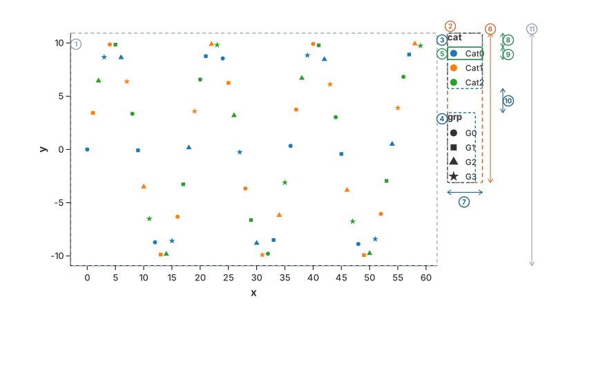
- ①
plot panel-- the area the data is drawn in. Everything the legend needs is measured against this rectangle, not against the whole canvas. - ②
strip-- the resolved legend plan: the bounding box of every block. Its size is what gets reserved as margin around the panel. - ③ ④
block-- one guide. A block contains its own title and all of its entries, so this is the box that is packed against the other blocks. - ⑤
entry-- one row of a legend: the symbol cell, the gap after the symbol, and the label text. It contains no spacing towards its neighbours; the packer adds the gaps. - ⑥
main-- the strip's length along the packing direction. A legend on the left or right edge is packed vertically, somainis a height: 216.4px here. - ⑦
cross-- the thickness across the packing direction (here the block width, 50.6px). It never decides whether something fits; it only decides how far the next column is offset when a run wraps. - ⑧ --
entry.ystarts at 20.2px rather than 0: a block's coordinates begin at its title, and the title strip (13.2px) plus its gap (7px) sit above the first entry. - ⑨ -- the step between two entries: row 18px +
legend_item_v_gap3px. - ⑩ --
legend_block_gap(35px). The second block's offset of 115.2px is the first block's height (80.2px) plus this gap. - ⑪
budget-- how long the strip may become: the panel's extent along the packing direction (336.6px here). The strip (⑥) has to stay within it, otherwise the legend spills over the axis line and covers the tick labels.
Two levels, one algorithm
Both levels -- the entries inside a block, and the blocks inside the strip -- are packed by the
same routine, so an offset always means the same thing: the top-left corner inside my parent. A
block sits at strip origin + block offset, an entry at block origin + entry offset, and the
renderer only ever adds those numbers together.
The direction is chosen once, from the legend position, and both levels obey it:
| Position | Direction | main is | cross is |
|---|---|---|---|
Top, Bottom | Horizontal | width | height |
Left, Right | Vertical | height | width |
Direction::measure(w, h) and Direction::resolve(main, cross) are a plain transpose, which is
why the one packing routine can serve both orientations.
Wrapping and the cursor
The cursor tracks where the next box of the current line begins, which is also how much of the
line is used. A box is placed while its far edge -- cursor + main -- stays inside the budget;
otherwise the run wraps and the next line is offset across the packing direction. The new line
starts after the thickest box of the previous line, never after its last box, so that a thick
box early in a line cannot be overlapped by the next one:
packing direction ->                      a legend with 30 categories, packed vertically
+------------------------------------+
| cat                                |    column 1 holds entries 0..14;
| ● Category 00   ● Category 15      |    the cursor reached 315px, and adding
| ● Category 01   ● Category 16      |    one more entry (18px) would have passed
| ...             ...                |    the budget of 316.4px, so entry 15
| ● Category 14   ● Category 29      |    starts a new column instead
+------------------------------------+
                    ^
   cross offset of column 2 = column width (93.8) + line gap (15) = 108.8
Two properties of the packer are worth stating explicitly, because the rest of the layout depends on them:
- Only
maindecides whether a box fits. A box is oversized only if it is longer than the whole budget on its own; then it is placed anyway, on a line of its own, and simply overflows. Callers that must not overflow have to checkmain_totalafterwards. - A line is as thick as its
max(cross). Wrapping advances by the line's thickest box, socrossnever affects placement inside a line, only where the next line starts.
Measuring one entry
A discrete entry is a single box that is fully determined by the theme and the label text:
|<-- cell=18 -->|<-- marker_text_gap -->|<----- label text ----->|
|      ●       |                       |      Category 00       |
|<------------------- entry main ------------------------------>|
-
cellis a fixed 18px square, so every symbol lines up in one column and every label starts at the same offset regardless of the glyph. -
row = max(18, legend_label_size). The entry's cross extent is always this row height. -
No spacing is baked into the box. The gaps are passed to the packer separately, and they swap with the direction so that lines stay tight while wraps stay readable:
Direction gap(within a line)line_gap(between lines)Horizontallegend_col_h_gaplegend_item_v_gapVerticallegend_item_v_gaplegend_col_h_gap
The budget handed to the entries is the panel's extent along the packing direction, minus the title when the title occupies that axis:
#![allow(unused)]
fn main() {
let entry_budget = match direction {
    Vertical   => (main_budget - title_height - title_gap).max(MIN_ENTRY_BUDGET), // 20px floor
    Horizontal => main_budget,
};
}
Measuring one block
A block is a title strip wrapped around the packed entries. The title is never an entry; it is added afterwards:
#![allow(unused)]
fn main() {
Vertical   => block main  = title_height + title_gap + packed.main_total
Horizontal => block cross = title_height + title_gap + packed.cross_total
width = width.max(estimate_text_width(title, title_height)) // a wide title widens the block
entries[i].y += title_height + title_gap                    // entries already sit below the title
}
title_height = legend_label_size * 1.1 (the title is slightly larger than the labels) and
title_gap = legend_title_gap. This is why the anatomy figure shows entry.y = 20.2px
(13.2 + 7) rather than 0.
Note what the reserved dimension is: for a vertical legend the height is the length along the packing direction and the width is the cross dimension. The strip reserves the cross thickness. The legend is not allowed to grow arbitrarily long; it must fit the panel it sits next to, and when it does not, it wraps and gets thicker. So the space taken from the panel is the result of wrapping, not an arbitrary demand.
Colour bars
A colour bar has no discrete entries, so it is measured from the budget directly:
| Direction | Length | Thickness |
|---|---|---|
Horizontal | main_budget.clamp(150, 300) | 15px |
Vertical | (main_budget * 0.7).min(200) | 15px |
Its tick labels sit under a horizontal bar and beside a vertical one, so the block's cross size is
thickness + padding + font in the first case and thickness + legend_marker_text_gap + max_label_width in the second. The tick set (colorbar_ticks) is shared by measurement and
rendering, so the widest label that was reserved for is the one that gets drawn.
Layout-Aware Rendering
Guides are not independent objects; they are aware of the chart's total physical constraints.
- Space Reservation: The layout engine asks the guides how much room they need and turns that into bands around the plot panel. A legend may never be longer than the panel it sits next to; that is the rule which keeps a long legend from covering the axis labels. The bands and the reservation loop are described in Space Manager.
- Anchoring: A guide is drawn inside the exact band that was reserved for it, so the reserved space and the drawn position always agree.
- Drawing verbatim: The resolved plan carries the final position of every block, every entry and every gradient bar. Renderers draw those numbers as they are instead of re-deriving them, which is what guarantees that the drawn legend matches the space reserved for it.
Why Consolidation Matters
The automated generation of these guides provides three core advantages:
- Mathematical Integrity: Because guides are generated directly from the resolved global scales, the labels are guaranteed to match the data precisely. You never have to manually update a label when the data changes.
- Reduced Visual Noise: By merging multiple aesthetics into a single legend block, the chart keeps the viewer's focus on the data, not on redundant interface elements.
- Automated Layout: Because the layout manager is aware of guide requirements, you don't need to manually configure margins. The chart automatically adjusts to accommodate the font sizes and number of categories present in your specific dataset.
Formatting Labels
By default Charton derives every label from the scale: pretty numbers with
scientific notation for axes, category names for legends. Production charts
routinely need more, so LabelFormat is the one builder for all of it:
currency prefixes, compact notation, fixed precision, thousands separators, or
an entirely custom string.
#![allow(unused)]
fn main() {
use charton::prelude::*;

let money = LabelFormat::new()
    .with_prefix("$")
    .with_compact_notation() // 20_000_000_000 -> 20B
    .with_precision(0);

chart!(year, investment)?
    .mark_line()?
    .encode((alt::x("year"), alt::y("investment"), alt::color("area")))?
    .with_y_label_format(money.clone())   // axis ticks
    .with_legend_label_format(money)      // legend entries / colour bar
    .to_svg()?;
}
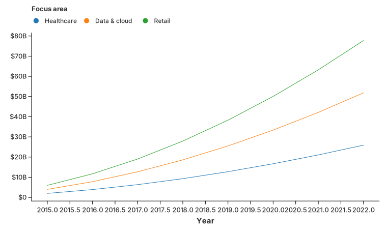
Three setters exist: with_x_label_format, with_y_label_format and
with_legend_label_format. The legend title is renamed with
with_color_label / with_shape_label / with_size_label, and the legend is
hidden completely with configure_theme(|t| t.with_show_legend(false)) (or
LegendPosition::None).
One formatting pass, at the scale
The formatter is applied by decorating the scale in a FormattedScale, not by
patching strings after the fact. That single decision is what keeps the guide
machinery self-consistent:
- Every consumer of the scale -- the axis renderer, the grid, the colour bar, and the layout engine that measures how much room the labels need -- sees the same strings. A formatted label that is wider than the raw one therefore reserves exactly the space it later occupies.
- Guide code must not re-derive labels. When a scale carries a formatter,
ScaleTrait::label_formatterreturnsSome, and the guide's decimal alignment pass (get_sampling_labels/get_sampling_ticks) returns the scale's labels untouched. - Visual mappings still key on the raw category values. The legend keeps a separate list of unformatted lookup labels, so uppercasing a legend label never changes which colour a category resolves to.
Escaping to arbitrary text
When the built-in options are not enough, hand the scale a closure:
#![allow(unused)]
fn main() {
// Continuous values
let custom = LabelFormat::new()
    .with_numeric_formatter(|value| format!("{:.1}%", value * 100.0));

// Categorical values
let custom = LabelFormat::new()
    .with_text_formatter(|label| label.replace('_', " "));
}
The closure produces the core text; with_prefix / with_suffix still apply
around it.
Key Takeaways
Axes map space; Legends map aesthetics.
- Guides are derived: They are not manually created, but are inferred directly from the Encoding and Scale specifications.
- Semantic Merging: Multiple aesthetics mapping to the same field are consolidated into a single guide to minimize visual clutter.
- Two levels, one packer: entries are packed into blocks, blocks into the strip, by the same flex-wrap routine in a
main/crossframe. - Layout Awareness: Guides communicate their size requirements to the layout engine, and the panel, the axes and the legends are resolved together by a short fixed-point loop.
- Known limitation: that loop is a fixed-point iteration over quantised values and is not guaranteed to converge; a rare period-2 oscillation can leave the legend layout one column off and flip it as the canvas is resized.
Industrial Mastery
Performance & Scaling
When a visualization library transitions from an academic prototype to an industrial-grade production tool, the primary bottleneck shifts from architectural expressiveness to raw computational performance. In enterprise environments, charts are routinely required to process millions of observation rows, compute complex statistical overlays in real time, and render under tight latency budgets.
Charton achieves sub-millisecond execution speeds on large-scale datasets by optimizing three distinct layers: hardware-friendly data ingestion, high-performance associative hashing, and streamlined geometric compilation.
Columnar Ingestion via Polars-Aligned Memory
Naive visualization tools often store data as rows of object instances, which introduces severe memory fragmentation and continuous pointer chasing. Charton eliminates this overhead by strictly enforcing a contiguous columnar memory layout.
As defined in the core data structures, a dataset is broken down into independent vectors of strongly typed primitives (ColumnVector variants such as Float64, Int32, or String).
- Polars Optimization: This layout mirrors the memory alignment used by the
PolarsDataFrame engine. Ingestion converts a Polars/Arrow source into these contiguous buffers in a single pass — values are copied, but there is no per-row pointer indirection and no JSON round-trip. - Cache Locality: By structuring data as contiguous primitive arrays (e.g.,
Vec<f64>), the CPU can efficiently pre-fetch values into its L1/L2 caches during axis scaling and coordinate transformations, maximizing hardware throughput.
High-Performance Hashing with ahash
Statistical marks—such as Box Plots and Kernel Density Estimations (KDE)—require the engine to group, bin, and partition continuous data rows based on categorical channels (like Color or X slots) before any drawing occurs. In standard implementations, these associative lookups represent a critical performance sink.
To solve this, Charton replaces Rust’s standard, cryptographically secure SipHasher with ahash (AHashMap and AHashSet) inside its core transform pipelines (transform_boxplot_data and transform_density_data).
$$\text{Throughput Gain} = \frac{\text{AHashMap Latency}}{\text{Standard Std Hash Latency}} \approx 3\times \text{ to } 5\times \text{ Acceleration}$$
Because visualization tasks operate within a controlled local context and do not require protection against Denial-of-Service (DoS) algorithmic attacks, ahash leverages customized hardware instructions (like AES-NI) to generate non-cryptographic hashes at a fraction of the CPU cycles. This ensures that grouping thousands of categorical intersections completes in microseconds.
Gap-Filling and Dense Categorical Alignment
When compiling complex multi-series statistical layouts (such as dodged box plots or stacked histograms), missing categories in certain sub-groups can break layout calculations, leading to uneven alignment grids.
Charton’s statistical transformers optimize this on-the-fly during the transformation step:
- Categorical Matrix Scanning: The transformer uses an
AHashMapto compile the global cartesian product of all available categorical keys. - Deterministic Gap Insertion: If a specific category combination lacks data points, the transformer automatically injects standard tracking boundaries or explicit
f64::NANrows. - Downstream Predictability: This dense padding guarantees that the layout engine receives perfectly balanced arrays, allowing visual positions to be calculated in single-pass vector operations without nested runtime checks.
Continuous Value Bound Sampling
For computationally heavy transformations like Kernel Density Estimation (KDE), evaluating the probability density at every single raw coordinate across millions of rows is redundant and slow. Charton optimizes the transformation pipeline by isolating boundary evaluations:
- Grid Sample Generation: The system scans the continuous target column to establish the true minimum and maximum global boundaries.
- Fixed Linear Interpolation: It then projects a fixed, customizable grid (e.g., 512 discrete sampling steps) between these boundaries.
- Vectorized KDE Execution: The underlying kernel functions (Normal, Epanechnikov, or Uniform) are evaluated exclusively against these synthesized grid points, turning an $O(N^2)$ point-cloud computation into an $O(N \cdot \text{Grid})$ linear operational pass.
Key Takeaways
- Columnar Layouts: Mirroring Arrow/Polars memory structures minimizes transformation copies and maximizes CPU cache locality.
- Ahash Acceleration: Relying on hardware-accelerated hashing makes grouping and categorizing thousands of data series practically free.
- Fixed Grid Transformations: Decoupling raw rows from evaluation steps prevents complex statistics (like KDE) from scaling exponentially with data size.
Publication-Ready Themes
In enterprise-grade data analysis and professional publishing workflows, visual consistency is non-negotiable. Graphs produced by different teams or across different project cycles must strictly adhere to a unified visual identity. Manual adjustments of font sizes, line widths, and padding for every single plot are not only inefficient but also highly prone to error.
Charton addresses this requirement through a fully decoupled, semantic Theme System. By separating data-driven graphic specifications from non-data aesthetics, this system enables the automated enforcement of standardized visual guidelines, ensuring that every chart—from internal dashboards to formal reports—maintains a professional and cohesive appearance.
Architectural Foundation of Themes
As defined in theme.rs, a Theme is an immutable, comprehensive configuration container. Unlike traditional plotting libraries that might hard-code layout margins or text properties within geometric renderers, Charton’s architecture treats styles as externalized constants.
These themes are injected into the rendering pipeline through PanelContext, allowing the same data layer to be styled differently simply by swapping the theme reference. The system governs three critical stylistic dimensions:
- Global Canvas & Spatial Margins: Controlled by parameters such as
top_margin,right_margin,bottom_margin, andleft_margin. These define the protective buffers around the canvas, ensuring that legends, titles, and axis elements do not bleed into the boundaries of the export surface. - Typographic Hierarchy: The system utilizes a font-stack strategy, governing specific layers—from
title_sizetotick_label_sizeandlegend_label_size. This ensures clear, readable visual hierarchy across different output resolutions. The stack syntax, per-glyph fallback and error behaviour are covered in Fonts & Text Rendering. - Visual Anchor Metrics: Geometric constraints such as
axis_width,tick_length,legend_block_gap, andlegend_marker_text_gap. By formalizing these metrics, the library maintains consistent layout density across varying chart complexities.
#![allow(unused)]
fn main() {
// Global theme injection ensures visual uniformity across all chart components.
let styled_chart = Chart::new(df)
    .mark_point()
    .encode((x("dosage"), y("efficacy")))
    .theme(Theme::corporate_standard()); // Enforces pre-defined visual guidelines
}
Layout-Safe Dynamic Adjustments
A primary challenge with static themes is that a layout ruleset might function perfectly for a simple scatter plot but fail in a dense, multi-panel (faceted) grid. Charton’s layout engine treats theme metrics as elastic constraints rather than fixed pixel values:
- The Axis Reserve Buffer: Defined in
theme.rsasaxis_reserve_buffer, this creates a defensive boundary around the plotting panel. When text labels rotate (viax_tick_label_angle), the layout engine dynamically calculates the required space based on the rotated bounding box, preventing text truncation or boundary collisions. - Panel Defense Ratio: To prevent oversized legends or long categorical labels from shrinking the core visualization area to a sliver, the system enforces a
panel_defense_ratio(defaulting to 0.2). This rule guarantees that no matter how many guide blocks are added to the outer regions, the central plotting area retains a significant percentage of the available canvas real estate.
Perceptually Uniform Palette Integration
Professional styling requires safeguarding the mathematical fidelity of continuous data. The theme engine integrates high-fidelity continuous mapping engines that prevent the artifacts common in naive RGB interpolation.
By utilizing predefined ColorMap strategies (such as Viridis or Magma), the theme ensures that data magnitude changes correspond linearly to human visual perception. This eliminates "false clustering"—a common visual bias in standard palettes—and ensures that every pixel accurately reflects the underlying data distribution.
Key Takeaways
- Complete Separation of Concerns: Data encodings (via
Chart<T>) define what is visualized, while theThemearchitecture dictates how it is physically presented. - Stateless Rendering: Renderers do not maintain internal style states; they query theme constants via
PanelContext, ensuring that visual updates are immediate and globally consistent. - Defensive Layout Guardrails: Mechanisms like
panel_defense_ratioandaxis_reserve_bufferensure that chart structural integrity is maintained automatically, even under complex or crowded layout conditions.
Safety & Error Registry
In high-performance visualization systems, the most costly errors are not rendering failures, but "logical mapping errors"—such as attempting to map continuous data to a discrete aesthetic channel, or misapplying coordinate scaling logic. Charton’s architecture is built on the philosophy of "Fail-Fast at Compile-Time" and "Structured Diagnostics."
Type-Safe Grammar and Validation
Charton’s core architecture enforces the legitimacy of its "Grammar of Graphics" at compile time, preventing developers from constructing invalid visual encodings.
- Generic Type Guards: Utilizing the state-machine pattern within
Chart<T>, Charton locks down operational logic via Rust's type system. For instance, statistical transformations liketransform_boxplot_dataare only accessible to specific mark types. Any attempt to apply unsupported operations triggers a compile-time error. - Channel-Scale Alignment: During the chart specification phase, the system validates the consistency between
Channel(e.g., Color, X, Y) and the requestedScale. By checking that the target data field matches the scale's domain, the system eliminates runtime "undefined mapping" risks.
Structured Error Registry
To ensure developers can rapidly diagnose complex visual issues, Charton replaces ambiguous error messages with a structured ChartonError enum. This registry centralizes the management of potential logical conflicts:
#![allow(unused)]
fn main() {
pub enum ChartonError {
    /// Error related to data handling or processing.
    #[error("Data error: {0}")]
    Data(String),
    /// Error related to mark definitions or configurations.
    #[error("Mark error: {0}")]
    Mark(String),
    /// Error related to encoding specifications.
    #[error("Encoding error: {0}")]
    Encoding(String),
}
}
Every error variant carries contextual metadata:
- Context-Aware Diagnostics: When the
LayoutEnginecalculates legend dimensions, if apanel_defense_ratioviolation occurs, the registry returns a detailed report containing the currentRectstate. This clearly identifies exactly which legend block caused the spatial overflow. - Recoverable Diagnostics: For non-fatal data issues (e.g., outliers slightly beyond the domain), the system supports "Soft Warning" modes. These warnings are logged in the registry, allowing the chart to perform automatic clipping instead of crashing.
Semantic Validation Pipeline
Before any Chart object proceeds to the render phase, it must pass through a Semantic Validation stage—a defensive "wall" designed to ensure structural integrity:
- Dimensional Validity: The system scans all
Encodingmappings. If aMarkPointis detected alongside incompatibleStackModeparameters (usually reserved forMarkAreaorMarkBar), the validator triggers a semantic error before expensive rendering begins. - Coordinate Scale Consistency: The system verifies that the coordinate system logic (e.g.,
Polarvs.Cartesian2D) matches the data's scale domains, preventing logical errors like using negative radial values in a polar chart. - CI/CD Integration: These error diagnostics can be serialized into JSON format. This allows for automated "Snapshot Testing" in CI/CD pipelines, where error-message hashes are compared to ensure that exception-handling mechanisms remain stable across library updates.
Key Takeaways
- Compile-Time Safety: Leveraging Rust's strong type system, we intercept incorrect mapping logic during development rather than in the production runtime.
- Structured Diagnostics: The error registry carries geometric context (panel sizes, coordinate parameters), significantly reducing the time required to debug complex layouts.
- Semantic Integrity: The validation pipeline acts as a protective layer, ensuring that all generated charts adhere to the mathematical and geometric logic of the "Grammar of Graphics."
Production Integration
For a visualization library to succeed in an industrial ecosystem, it must extend beyond local rendering. It must integrate seamlessly into CI/CD pipelines, support automated regression testing, and provide deterministic output across various deployment environments—whether that is a cloud-native microservice, a WASM-powered browser interface, or a static report generation tool.
Automated Regression & Snapshot Testing
Visual libraries are notoriously difficult to test because the "correct" output is often subjective. Charton addresses this by implementing a Snapshot-Based Testing architecture.
- Binary Snapshotting: Since Charton generates SVGs or binary image buffers through defined backends, we can serialize the output of a chart specification into a reference file. During CI, the library renders the chart and compares the output byte-by-byte (or via fuzzy perceptual hashing) against the golden master.
- Deterministic Configuration: By forcing all layouts to rely on the
ThemeandCoordinatesystems, we eliminate non-determinism caused by OS-specific font rendering or system-level float rounding, ensuring that a chart generated on a developer’s machine matches the production CI build exactly.
CI/CD Pipeline Integration
Charton is engineered to be a "headless" citizen of the cloud. The core rendering pipeline and the SvgBackend / RasterBackend / PdfBackend / WgpuBackend implementations are optimized for containerized environments:
- Minimal Footprint: By utilizing high-performance columnar data layouts, Charton ensures that memory overhead remains flat even when processing datasets that would crash standard plotting tools. This makes it ideal for running in restricted-resource container environments (e.g., AWS Lambda, K8s sidecars).
- Feature Flagging: Output formats (PNG, PDF, etc.) are gated behind
Cargofeatures (png/raster,pdf,wgpu,geo,arrow,parallel). This allows production builds to prune unnecessary dependencies, drastically reducing the binary size and attack surface in production environments.
Deployment Strategies
When deploying Charton-powered services, we recommend two distinct patterns depending on the load:
| Deployment Pattern | Use Case | Implementation Strategy |
|---|---|---|
| Edge Rendering (WASM) | Interactive UI / Dashboards | Compile the core library to WASM for client-side rendering, minimizing server load. |
| Headless Batch Service | Automated Report Generation | Use a containerized Rust service to consume IPC data, render to SVG/PNG, and pipe to S3. |
Semantic Validation in CI
The Semantic Validation pipeline described in our Error Registry is essential for production stability. Before a deployment is cleared:
- Schema Check: CI runners parse the user-provided ChartSpec and perform a static analysis to ensure all channels (X, Y, Color) are bound to valid data types.
- Bounds Audit: The pipeline evaluates the dataset range against the ScaleDomain. If the system detects potential data overflow or empty domains before rendering, the build fails immediately, preventing "blank chart" incidents in the production dashboard.
Key Takeaways
Deterministic Outputs: Leverage snapshot testing to ensure that cross-environment chart generation yields identical visual results.
Resource Optimization: Use feature-gated builds and columnar data handling to ensure high-throughput rendering within containerized cloud environments.
Headless Capability: Design services for headless batch processing by treating the rendering engine as a pure, stateless function that transforms Dataset + Theme into a serialized visual artifact.
Recipe Index
Named, copy-paste recipes for the charts people ask for by name. Each links to a complete, compiled example — the image you see is the output of the code right below it — and to the primitives it is built from.
The convenience marks (
mark_violin,mark_density,mark_contour,mark_density_2d, …) are just names for common compositions, so every entry's "Built from" column shows both the mark and the primitives it expands into. If your chart is missing, build it from the Marks & Geometries vocabulary and the layer pipeline, then add it here.
Distributions
| Recipe | Also known as | Built from |
|---|---|---|
| Density plot | KDE | mark_density (transform_density + mark_area) |
| Density heatmap | 2-D KDE | mark_density_2d (transform_density_2d + mark_rect) |
| Density contour | 2-D KDE iso-lines | mark_contour over transform_density_2d |
| Cumulative density | KDE integral | mark_density (cumulative) |
| Empirical CDF | cumulative frequency | transform_window (CumeDist) |
| Violin | density outline, upright | mark_violin |
| Grouped violin | dodged violin | mark_violin (x + color, dodge) |
| Faceted violin | small multiples | mark_violin + facet |
| Split violin | mark_violin (split) | |
| Raincloud | mark_violin + transform_quantile_box + jittered points | |
| Ridgeline | joyplot | transform_density + transform_band (split) + mark_polygon |
| Violin with inner box | mark_violin + transform_quantile_box | |
| Box plot | box & whiskers | mark_boxplot |
| Histogram | mark_hist | |
| Scatter | mark_point + shape/size/color | |
| Beeswarm | swarm | mark_point + layout |
| Quasirandom | dot plot | mark_point + layout |
| Strip plot | rug | mark_tick |
| Styled strip | mark_tick + configure_tick |
Comparisons
| Recipe | Also known as | Built from |
|---|---|---|
| Bar with error bars | mean ± error | mark_bar + mark_errorbar |
| Grouped bar with error bars | mark_bar + mark_errorbar + Position::dodge | |
| Stacked bar | mark_bar + stack | |
| Error bar | mark_errorbar | |
| Dumbbell | connected dot | mark_rule + mark_point |
| Lollipop | mark_rule + mark_point | |
| Range plot | intervals | mark_rule (y + y2) |
| Waterfall | running total | mark_bar (y2) + transform_window (CumulativeSum) |
| Candlestick | OHLC | mark_rule + mark_bar (y2) |
Trends & time
| Recipe | Also known as | Built from |
|---|---|---|
| Line (multiple series) | mark_line + color | |
| Cumulative frequency | mark_line | |
| Multi-series with error bars | mark_line + mark_errorbar + mark_point | |
| Formatted axis labels | $20B-style | with_y_label_format |
| Slope chart | mark_line + mark_point | |
| Bump chart | ranking | transform_window (Rank) + reversed axis |
| Area chart | mark_area | |
| Simple stacked area | mark_area + stack: stacked | |
| Normalized stacked area | 100% area | mark_area + stack: normalize |
| Steamgraph | streamgraph | mark_area + stack: center |
Matrices & relationships
| Recipe | Also known as | Built from |
|---|---|---|
| Scatter | mark_point + shape/size/color | |
| Categorical heatmap | mark_rect | |
| Continuous heatmap | 2-D histogram | mark_rect + binning |
| Iso-lines of a grid | contour plot | mark_contour (transform_contour + mark_path) |
| Single-colour contour | mark_contour without colour-by-level | |
| Density contours | 2-D KDE | mark_contour over transform_density_2d |
Circular
| Recipe | Also known as | Built from |
|---|---|---|
| Pie | mark_bar + CoordSystem::Polar | |
| Donut | pie + inner radius | |
| Rose | polar bar | mark_bar + polar |
| Nightingale | coxcomb | mark_bar + polar |
Layout & special
| Recipe | Also known as | Built from |
|---|---|---|
| Facet grid | small multiples | facet |
| World map | choropleth | mark_geoshape + CoordSystem::Geo |
Choosing a distribution view
- Histogram — a first, honest look at the shape.
- Density — the same shape, smoothed; good when the distribution is interesting.
- Box plot — compact and precise about quartiles, hides the shape.
- Violin — the shape with quartiles available as an inner box.
- Ridgeline — many distributions compared at once, one density per category.
- Beeswarm / strip — every observation; good for small samples.
See Missing Values & Gaps for how each view handles nulls and gaps.
Going deeper
- Composing Your Own — recombining the primitives into new pictures the marks do not cover.
- Contour Plots — the marching-squares machinery and the general scalar-grid contour.
- Transforms & Columns — the column contract of every transform used by these recipes.
Histogram
mark_hist bins a numeric column for you and draws the counts as bars — the
classic first look at a distribution. The bin count follows from the data unless
you set alt::x(...).with_bins(n).
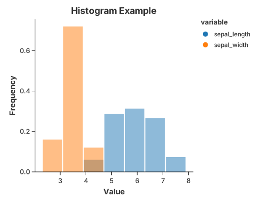
use charton::prelude::*;
use std::error::Error;

fn main() -> Result<(), Box<dyn Error>> {
    let ds = load_dataset("iris")?;
    println!("{:?}", ds);

    let raw_sl = ds.get_column::<f64>("sepal_length")?;
    let raw_sw = ds.get_column::<f64>("sepal_width")?;

    let mut value = Vec::with_capacity(raw_sl.len() + 50);
    value.extend_from_slice(raw_sl);
    value.extend_from_slice(&raw_sw[0..50]);

    let mut variable = Vec::with_capacity(raw_sl.len() + 50);
    variable.extend(std::iter::repeat_n(
        "sepal_length".to_string(),
        raw_sl.len(),
    ));
    variable.extend(std::iter::repeat_n("sepal_width".to_string(), 50));

    // Create a histogram chart
    let histogram = chart!(value, variable)?
        .mark_hist()?
        .configure_hist(|h| {
            h.with_color("steelblue")
                .with_opacity(0.5)
                .with_stroke("black")
                .with_stroke_width(0.0)
        })
        .encode((
            alt::x("value"),
            alt::y("count").with_normalize(true),
            alt::color("variable"),
        ))?;

    histogram
        .with_size(500, 400)
        .with_title("Histogram Example")
        .with_x_label("Value")
        .with_y_label("Frequency")
        .configure_theme(|t| t.with_palette(ColorPalette::Tab10))
        .save("docs/src/images/histogram.svg")?;

    Ok(())
}
Add a color field to overlay several columns in one frame, and
alt::y("count").with_normalize(true) to read frequencies instead of raw counts.
See also
- 1-D Density — the smoothed version of the same picture.
- Bars, Ranges & Comparisons —
mark_barwhen you already have the counts.
1-D Density
A one-dimensional density estimate (a KDE) draws the shape of a numeric column as a smooth curve — the smooth counterpart of a histogram.
mark_density is the convenient way to draw one. It is a composite mark:
behind the scenes it expands into the ordinary recipe
transform_density   // numeric column  →  (value, density)
  → mark_area       // draw the curve
so you can always drop to the pieces. The last section writes the same picture out by hand.
Density plot
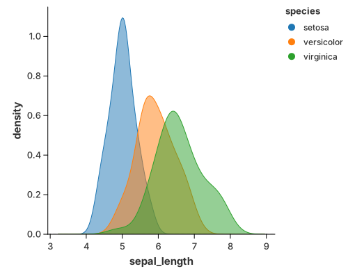
Read the value from x; each color group gets its own curve.
//! Density plot — the convenience `mark_density`.
//!
//! `mark_density` is a **composite** mark: it expands into the public
//! `transform_density` and the shared area geometry. For the composition written
//! out by hand, see `density_manual.rs`. It is the smooth counterpart of a
//! histogram; a violin is the same curve stood upright and mirrored.

use charton::prelude::*;

fn main() -> Result<(), Box<dyn std::error::Error>> {
    let ds = load_dataset("iris")?;

    chart!(ds)?
        .mark_density()?
        .configure_density(|density| density.with_opacity(0.5))
        .encode((alt::x("sepal_length"), alt::color("species")))?
        .save("docs/src/images/density.svg")?;

    Ok(())
}
By default the estimator keeps the tails (trim = false), so the curve fades out
past the last observation — the geom_density look. A violin is the very same
curve stood upright and mirrored; see Violin.
Tuning the curve
Estimating the curve (statistics) and drawing it (geometry) are configured
separately. configure_density forwards the estimator options:
| Method | Meaning |
|---|---|
configure_density(…).with_bandwidth(BandwidthType::Silverman) | smoothing rule (Scott by default) |
.with_kernel(KernelType::Epanechnikov) | smoothing kernel |
.with_trim(true) | stop each curve at its own data range instead of the shared grid |
.with_counts(true) | scale each curve by its group size (counts, not density) |
.with_cumulative(true) | draw the cumulative distribution instead |
.with_color(…), .with_opacity(…), .with_stroke(…) | the area's visual style |
The underlying transform_density replaces the table: it reads the numeric
column and emits (value, density) plus one column per groupby field. See
Transforms & Columns for the full column contract.
Built from the primitives
The same picture without mark_density: transform_density estimates the curve
and mark_area draws it.
//! Density plot — built by hand from the primitives.
//!
//! The same picture as `density.rs`, without `mark_density`. A one-dimensional
//! density estimate (a KDE) draws the shape of a numeric column as a smooth
//! curve: `transform_density` estimates the curve and `mark_area` draws it.
//!
//! ```text
//! transform_density   // numeric column  →  (value, density)
//!   → mark_area       // draw the curve
//! ```

use charton::prelude::*;
use std::error::Error;

fn main() -> Result<(), Box<dyn Error>> {
    let ds = load_dataset("iris")?;

    chart!(ds)?
        .transform_density(
            DensityTransform::new("sepal_length")
                .with_as("sepal_length", "density")
                .with_groupbys(["species"]),
        )?
        .mark_area()?
        .configure_area(|a| a.with_opacity(0.5))
        .encode((
            alt::x("sepal_length"),
            alt::y("density"),
            alt::color("species"),
        ))?
        .save("target/example-output/density_manual.svg")?;

    Ok(())
}
See also
- Composing Your Own — recombining the primitives into new pictures the marks do not cover.
- Violin — the upright, mirrored form, and its grouped/split layouts.
- 2-D Density — two columns at once.
- Cumulative Density — the integral of the curve.
2-D Density
A two-dimensional density estimate describes the joint distribution of two
numeric columns. transform_density_2d estimates it on a regular grid; the same
grid can then be drawn two ways, both as composite marks:
transform_density_2d                 // (x, y)  →  (x, y, density) grid
  ├─ mark_density_2d                 // filled density heatmap
  └─ mark_contour("density")         // iso-density lines
Neither mark hides anything: they expand into transform_density_2d plus the
public mark_rect / transform_contour geometry, so the hand-written recipe is
always available (see the column contract).
Density heatmap
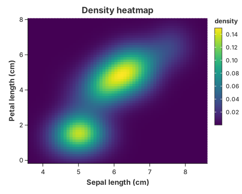
Read the two columns from x and y; the mark estimates the joint density and
paints one cell per grid node, coloured by the density.
//! Density heatmap — a bivariate kernel density drawn as a grid of cells, with
//! `mark_density_2d`.
//!
//! `mark_density_2d` is a **composite** mark: it expands into the public
//! `transform_density_2d` and the shared rectangle geometry. It sets the heatmap
//! bin count to the grid size automatically, so the caller does not have to know
//! that `mark_rect` bins a second time. This is the filled counterpart of the
//! density contour.

use charton::prelude::*;
use std::error::Error;

fn main() -> Result<(), Box<dyn Error>> {
    let iris = load_dataset("iris")?;

    chart!(iris)?
        .mark_density_2d()?
        .configure_density_2d(|density| density.with_grid_size(60).with_padding(0.2))
        .encode((alt::x("sepal_length"), alt::y("petal_length")))?
        .configure_theme(|t| t.with_color_map(ColorMap::Viridis))
        .with_title("Density heatmap")
        .with_x_label("Sepal length (cm)")
        .with_y_label("Petal length (cm)")
        .save("docs/src/images/density_heatmap.svg")?;

    println!("Saved docs/src/images/density_heatmap.svg");
    Ok(())
}
Building it by hand is transform_density_2d followed by mark_rect. mark_rect
paints one cell per grid node, so you must set the x and y bins to the grid
size or the cells get merged back together — mark_density_2d does that for you.
Density contours
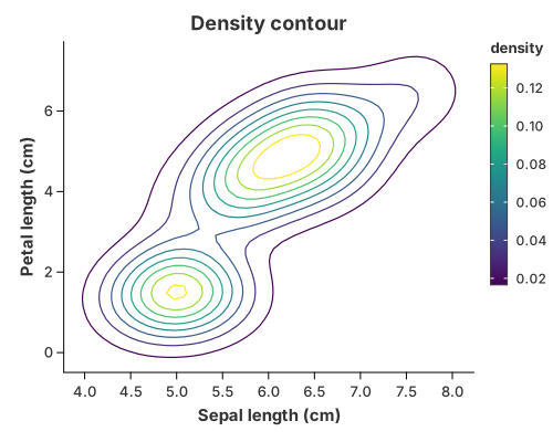
The same grid can be passed to mark_contour("density"), which turns it into
iso-lines. Colour them by level for the familiar kdeplot /
geom_density_2d picture, or drop the colour for a single-colour contour.
//! Density contour — iso-lines of a bivariate kernel density, with
//! `mark_contour`.
//!
//! The scattered points are first summarised into a density grid by the public
//! `transform_density_2d`, then `mark_contour("density")` turns that grid into
//! iso-lines and draws them. So the mark handles the contouring; the density
//! estimate stays an explicit, reusable step.

use charton::prelude::*;
use std::error::Error;

fn main() -> Result<(), Box<dyn Error>> {
    let iris = load_dataset("iris")?;

    chart!(iris)?
        // 1. Estimate the joint density of the two measurements.
        .transform_density_2d(
            // Pad the estimation grid so the outer iso-lines close before its
            // edge instead of being clipped by it.
            Density2DTransform::new("sepal_length", "petal_length")
                .with_grid_size(60)
                .with_padding(0.3),
        )?
        // 2. Extract and draw iso-density lines (coloured by level by default).
        .mark_contour("density")?
        .configure_contour(|contour| contour.with_levels(8).with_stroke_width(1.2))
        .encode((alt::x("x"), alt::y("y")))?
        .configure_theme(|t| t.with_color_map(ColorMap::Viridis))
        .with_title("Density contour")
        .with_x_label("Sepal length (cm)")
        .with_y_label("Petal length (cm)")
        .save("docs/src/images/density_contour.svg")?;

    println!("Saved docs/src/images/density_contour.svg");
    Ok(())
}
The column contract
When you build these by hand, both steps replace the table, so you need to know the columns each one emits:
| Call | Reads | Emits |
|---|---|---|
transform_density_2d(x, y) | two numeric columns | x, y, density |
transform_contour(x, y, z) | the grid | x, y, path_group, level |
density is consumed by the contour step, so it never appears in encode.
Rename the outputs with Density2DTransform::with_as and
ContourTransform::with_as / with_level_as. This is the canonical list for
both transforms; the hand-written wire-up is on the
Contour Plots page.
Tuning the estimate
configure_density_2d forwards the estimator options:
| Method | Meaning |
|---|---|
configure_density_2d(…).with_grid_size(n) | grid nodes per axis (default 50) |
.with_padding(f) | widen the grid past the data so the tails are visible |
.with_bandwidth(BandwidthType::Silverman) | smoothing rule |
.with_color(…), .with_opacity(…), .with_stroke(…) | the cell visual style |
For a contour, a dashed line is
configure_contour(\|m\| m.with_dash([6.0, 4.0])).
See also
- Contour Plots — the general marching-squares contour, for any scalar grid.
- Heatmaps —
mark_rectover binned data. - Composing Your Own — recombining the primitives into new pictures.
- Transforms & Columns.
Cumulative Density
A cumulative density is the integral of a density curve: the share of the data at or below each value. It rises from 0 to 1 and reads the same as an empirical CDF, but is smoothed by the same kernel used for the 1-D density.
mark_density draws it with configure_density(…).with_cumulative(true); behind
the scenes that is still the ordinary recipe
transform_density(cumulative = true)   //  →  (value, cumulative density)
  → mark_area
Cumulative density curve
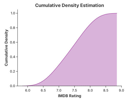
//! Cumulative density — the convenience `mark_density` with `with_cumulative`.
//!
//! A cumulative density is the integral of a density curve: the share of the
//! data at or below each value. It rises from 0 to 1 and reads like an empirical
//! CDF, but is smoothed by the same kernel used for the 1-D density. For the
//! composition written out by hand, see `distribution_manual.rs`.

use charton::prelude::*;
use std::error::Error;

fn main() -> Result<(), Box<dyn Error>> {
    // Create sample data for demonstration
    let imdb_rating = [
        7.1, 6.8, 7.5, 8.2, 6.9, 7.3, 7.7, 8.0, 6.5, 7.2, 7.9, 6.7, 7.4, 7.8, 8.1, 6.6, 7.0, 7.6,
        8.3, 6.4, 7.2, 7.5, 7.9, 6.8, 7.1, 7.7, 8.0, 6.9, 7.3, 7.6, 7.4, 7.8, 8.2, 6.7, 7.0, 7.5,
        7.9, 6.6, 7.1, 7.7,
    ];
    let genre = [
        "Action", "Drama", "Action", "Comedy", "Drama", "Action", "Comedy", "Drama", "Action",
        "Comedy", "Drama", "Action", "Comedy", "Drama", "Action", "Comedy", "Drama", "Action",
        "Comedy", "Drama", "Action", "Comedy", "Drama", "Action", "Comedy", "Drama", "Action",
        "Comedy", "Drama", "Action", "Comedy", "Drama", "Action", "Comedy", "Drama", "Action",
        "Comedy", "Drama", "Action", "Comedy",
    ];
    let year = [
        2010, 2011, 2010, 2012, 2011, 2010, 2013, 2012, 2011, 2010, 2014, 2013, 2012, 2011, 2010,
        2015, 2014, 2013, 2012, 2011, 2010, 2016, 2015, 2014, 2013, 2012, 2011, 2010, 2017, 2016,
        2015, 2014, 2013, 2012, 2011, 2010, 2018, 2017, 2016, 2015,
    ];

    chart!(imdb_rating, genre, year)?
        .mark_density()?
        .configure_density(|density| {
            density
                .with_cumulative(true)
                .with_color("purple")
                .with_opacity(0.3)
        })
        .encode(alt::x("imdb_rating"))?
        .with_title("Cumulative Density Estimation")
        .with_x_label("IMDB Rating")
        .with_y_label("Cumulative Density")
        .save("docs/src/images/distribution.svg")?;

    Ok(())
}
Empirical CDF (cumulative frequency)
When you want the exact, unsmoothed version, use a window CumeDist and draw it
as a step line. No binning or smoothing is involved — every observation is a
step.
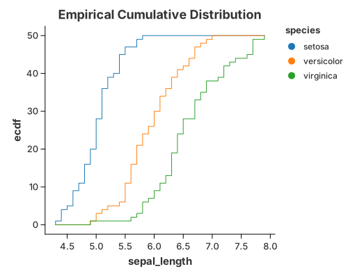
use charton::prelude::*;
use std::error::Error;

fn main() -> Result<(), Box<dyn Error>> {
    let ds = load_dataset("iris")?;
    // Create a chart with window transform
    chart!(ds)?
        .transform_window(
            WindowTransform::new(WindowFieldDef::new(
                "sepal_length",
                WindowOnlyOp::CumeDist,
                "ecdf", // This will be the output column name
            ))
            .with_groupbys(["species"])
            .with_normalize(false),
        )?
        .mark_line()?
        .configure_line(|l| l.with_interpolation("step")) // Add step interpolation
        .encode((
            alt::x("sepal_length"),
            alt::y("ecdf"),
            alt::color("species"),
        ))?
        .with_title("Empirical Cumulative Distribution")
        .save("docs/src/images/cumulative_frequency.svg")?;

    Ok(())
}
Both pictures answer "what fraction is below x?", one smooth and one as a step
function. Use transform_window(WindowOnlyOp::CumeDist) for the exact ECDF,
mark_density with with_cumulative(true) for the kernel-smoothed curve.
Built from the primitives
The same picture without mark_density: set .with_cumulative(true) on
DensityTransform and draw the curve with mark_area.
//! Cumulative density — built by hand from the primitives.
//!
//! The same picture as `distribution.rs`, without `mark_density`:
//! `transform_density(cumulative = true)` estimates the curve and `mark_area`
//! draws it.

use charton::prelude::*;
use std::error::Error;

fn main() -> Result<(), Box<dyn Error>> {
    // Create sample data for demonstration
    let imdb_rating = [
        7.1, 6.8, 7.5, 8.2, 6.9, 7.3, 7.7, 8.0, 6.5, 7.2, 7.9, 6.7, 7.4, 7.8, 8.1, 6.6, 7.0, 7.6,
        8.3, 6.4, 7.2, 7.5, 7.9, 6.8, 7.1, 7.7, 8.0, 6.9, 7.3, 7.6, 7.4, 7.8, 8.2, 6.7, 7.0, 7.5,
        7.9, 6.6, 7.1, 7.7,
    ];
    let genre = [
        "Action", "Drama", "Action", "Comedy", "Drama", "Action", "Comedy", "Drama", "Action",
        "Comedy", "Drama", "Action", "Comedy", "Drama", "Action", "Comedy", "Drama", "Action",
        "Comedy", "Drama", "Action", "Comedy", "Drama", "Action", "Comedy", "Drama", "Action",
        "Comedy", "Drama", "Action", "Comedy", "Drama", "Action", "Comedy", "Drama", "Action",
        "Comedy", "Drama", "Action", "Comedy",
    ];
    let year = [
        2010, 2011, 2010, 2012, 2011, 2010, 2013, 2012, 2011, 2010, 2014, 2013, 2012, 2011, 2010,
        2015, 2014, 2013, 2012, 2011, 2010, 2016, 2015, 2014, 2013, 2012, 2011, 2010, 2017, 2016,
        2015, 2014, 2013, 2012, 2011, 2010, 2018, 2017, 2016, 2015,
    ];

    let chart = chart!(imdb_rating, genre, year)?
        .transform_density(
            DensityTransform::new("imdb_rating")
                .with_as("imdb_rating", "cumulative_density")
                .with_cumulative(true),
        )?
        .mark_area()?
        .configure_area(|a| a.with_color("purple").with_opacity(0.3))
        .encode((alt::x("imdb_rating"), alt::y("cumulative_density")))?;

    chart
        .with_title("Cumulative Density Estimation")
        .with_x_label("IMDB Rating")
        .with_y_label("Cumulative Density")
        .save("target/example-output/distribution_manual.svg")?;

    Ok(())
}
See also
Violin
A violin shows the density of a numeric value as a symmetric outline.
mark_violin is the convenient way to draw one. It is a composite mark:
behind the scenes it expands into the ordinary recipe
transform_density(trim = true)        // one curve per category (and group)
  → a symmetric outline               // transform_band polygon
  → the shared polygon renderer
so nothing is hidden that you cannot write yourself. The recipes below use the mark; the last section writes the same picture out of the primitives, for anyone who wants to recombine the pieces. The curve itself (bandwidth, kernel, trim) is described in 1-D Density.
Violin (single)
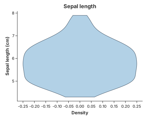
Read the value from y; the mark estimates its density and draws the symmetric
outline.
//! Violin plot — the convenience `mark_violin`.
//!
//! `mark_violin` is a **composite** mark: it expands into the ordinary public
//! recipe `transform_density` → `transform_band` → the shared polygon renderer.
//! For power users who want to build it themselves, `violin_manual.rs` writes the
//! same picture out of those primitives.
//!
//! The inputs come from the encodings:
//!
//! * `y` — the numeric value whose density is drawn (required);
//! * `x` — an optional category each violin sits on;
//! * `color` — an optional group that splits a category into lanes.

use charton::prelude::*;
use std::error::Error;

fn main() -> Result<(), Box<dyn Error>> {
    let iris = load_dataset("iris")?;

    chart!(iris)?
        .mark_violin()?
        .configure_violin(|violin| {
            violin
                .with_color("#7fb3d5")
                .with_opacity(0.6)
                .with_stroke("#2c3e50")
        })
        .encode(alt::y("sepal_length"))?
        .with_title("Sepal length")
        .with_x_label("Density")
        .with_y_label("Sepal length (cm)")
        .save("docs/src/images/violin.svg")?;

    println!("Saved docs/src/images/violin.svg");
    Ok(())
}
Grouped and faceted violins
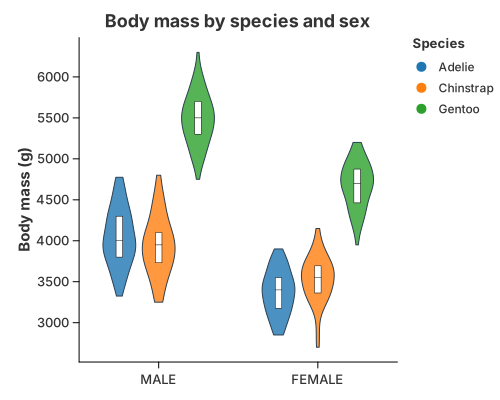
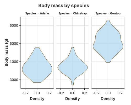
Two industry layouts, both one call to mark_violin plus the encodings:
- Faceted (Vega-Lite / Altair style): read only
yandfacetby the group, so each panel gets its own violin. - Dodged (ggplot2 style): map
xto the category andcolorto the group; the mark dodges the lanes side by side. The inner box is an ordinarytransform_quantile_boxlayer, drawn on top with.and(…).
//! Grouped violins — the two industrial layouts, with `mark_violin`.
//!
//! * **Faceted** (Vega-Lite / Altair style): one violin per panel.
//! * **Dodged** (ggplot2 style): the violins sit side by side inside each
//!   category, and an ordinary `transform_quantile_box` layer draws the inner
//!   box.
//!
//! The penguins `Sex` column has a couple of missing values. `Sex` is the
//! *positional* category here, so those rows are dropped, exactly as ggplot2 and
//! Altair would — no stray `null` violin appears, and the outline and its inner
//! box always agree because both use the shared lane layout.

use charton::prelude::*;
use std::error::Error;

fn main() -> Result<(), Box<dyn Error>> {
    let penguins = load_dataset("penguins")?;

    // === 1. Faceted: one violin per panel ==================================
    chart!(&penguins)?
        .mark_violin()?
        .configure_violin(|violin| violin.with_opacity(0.7).with_stroke("#7e5109"))
        .encode(alt::y("Body Mass (g)"))?
        .facet(FacetSpec::wrap("Species").with_columns(3))
        .with_title("Body mass by species")
        .with_x_label("Density")
        .with_y_label("Body mass (g)")
        .save("docs/src/images/faceted_violin.svg")?;

    // === 2. Dodged: side by side inside each Sex, with an inner box ========
    let outline = chart!(&penguins)?
        .mark_violin()?
        .configure_violin(|violin| violin.with_color("#d6eaf8").with_stroke("#2c3e50"))
        .encode((
            alt::x("Sex"),
            alt::y("Body Mass (g)"),
            alt::color("Species"),
        ))?;

    let inner_box = chart!(&penguins)?
        .transform_quantile_box(
            QuantileBoxTransform::new("Body Mass (g)")
                .with_category("Sex")
                .with_group("Species")
                .with_position(Position::dodge()),
        )?
        .mark_polygon()?
        .configure_geoshape(|mark| mark.with_fill("white").with_stroke("black"))
        .encode((
            alt::x("x").with_category_labels("Sex"),
            alt::y("y"),
            alt::path_group("path_group"),
        ))?;

    outline
        .and(inner_box)
        .with_title("Body mass by species and sex")
        .with_x_label("")
        .with_y_label("Body mass (g)")
        .save("docs/src/images/grouped_violin.svg")?;

    println!("Saved docs/src/images/faceted_violin.svg and grouped_violin.svg");
    Ok(())
}
When a category used for position is missing (the penguins Sex column has a
few), that row is dropped, exactly as ggplot2 and Altair would — no null violin
appears. A missing group (the colour/lane) behaves differently: it is kept as
a grey NA lane. See Missing Values & Gaps.
Split violin
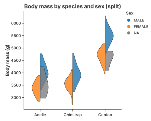
One centre line per category, the first group growing right and the second left:
mark_violin with configure_violin(…).with_split(true). Colour the result by
group and the two halves read as a single violin split down the middle.
//! Split violin — two groups as the left and right halves of one violin, with
//! `mark_violin`.
//!
//! Set `with_split(true)` and colour by the group: the first group grows to the
//! right of each centre and the second to the left. The mark expands this into
//! the ordinary density transform plus the general band geometry in `split`
//! mode, so each half is an ordinary polygon.

use charton::prelude::*;
use std::error::Error;

fn main() -> Result<(), Box<dyn Error>> {
    let penguins = load_dataset("penguins")?;

    chart!(&penguins)?
        .mark_violin()?
        .configure_violin(|violin| {
            violin
                .with_split(true)
                .with_color("#95a5a6")
                .with_stroke("#2c3e50")
        })
        .encode((
            alt::x("Species"),
            alt::y("Body Mass (g)"),
            alt::color("Sex"),
        ))?
        .with_title("Body mass by species and sex (split)")
        .with_x_label("")
        .with_y_label("Body mass (g)")
        .save("docs/src/images/split_violin.svg")?;

    println!("Saved docs/src/images/split_violin.svg");
    Ok(())
}
This is the general transform_band(…).with_split(true) geometry underneath: the
two groups share the centre line instead of sitting in separate lanes.
Raincloud
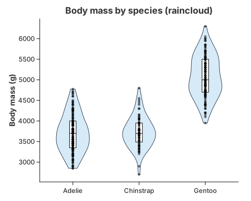
Three views of the same distribution, stacked with .and(…): the violin
outline, an inner inter-quartile box from transform_quantile_box, and every
observation as a jittered point layer.
//! Raincloud — a violin outline, an inner box and the raw observations.
//!
//! The raincloud is the clearest demonstration of the layer model: three views
//! of the same distribution, each an ordinary mark, stacked with `.and(…)`.
//!
//! * `mark_violin`              → the density outline
//! * `transform_quantile_box`   → the inter-quartile box and median
//! * `mark_point` + jitter      → every observation
//!
//! All three share the same x and y scales, so they line up automatically.

use charton::prelude::*;
use std::error::Error;

fn main() -> Result<(), Box<dyn Error>> {
    let penguins = load_dataset("penguins")?;

    // 1. The cloud: a density outline per species, straight from `mark_violin`.
    let violin = chart!(&penguins)?
        .mark_violin()?
        .configure_violin(|mark| {
            mark.with_color("#d6eaf8")
                .with_opacity(1.0)
                .with_stroke("#2c3e50")
                .with_stroke_width(1.0)
        })
        .encode((alt::x("Species"), alt::y("Body Mass (g)")))?;

    // 2. The box: the quartiles, drawn from the same raw observations.
    let inner_box = chart!(&penguins)?
        .transform_quantile_box(
            QuantileBoxTransform::new("Body Mass (g)").with_category("Species"),
        )?
        .mark_polygon()?
        .configure_geoshape(|mark| {
            mark.with_fill("white")
                .with_stroke("black")
                .with_stroke_width(1.0)
        })
        .encode((
            alt::x("x").with_category_labels("Species"),
            alt::y("y"),
            alt::path_group("path_group"),
        ))?;

    // 3. The rain: every observation, jittered inside the violin.
    let rain = chart!(&penguins)?
        .mark_point()?
        .configure_point(|point| {
            point
                .with_layout("jitter")
                .with_size(2.5)
                .with_opacity(0.55)
        })
        .encode((alt::x("Species"), alt::y("Body Mass (g)")))?;

    violin
        .and(inner_box)
        .and(rain)
        .with_title("Body mass by species (raincloud)")
        .with_x_label("")
        .with_y_label("Body mass (g)")
        .save("docs/src/images/raincloud.svg")?;

    println!("Saved docs/src/images/raincloud.svg");
    Ok(())
}
Tuning the violin
Shape options live in 1-D Density; these control the mark and its lanes:
| Method | Meaning |
|---|---|
configure_violin(…).with_bandwidth(BandwidthType::Silverman) | smoothing rule (Scott by default) |
.with_trim(true) | stop each curve at its own data range (the default for violins) |
.with_split(true) | draw two groups as one split violin |
.with_scale(BandScale::PerGroup) | every band has the same maximum width (default) |
.with_scale(BandScale::Global) | bands share one scale, so a denser group looks wider |
.with_scale(BandScale::Raw) | use the width column as it stands |
.with_width(0.5) | maximum width of a single band (matches the box plot) |
.with_side(BandSide::Right) | keep one bank of the violin (a half violin / ridgeline) |
.with_overlap(2.5) | grow each band past its lane so neighbours overlap |
.with_span(0.7) | total width of a category's group (matches the box plot and point marks) |
.with_color(…), .with_opacity(…), .with_stroke(…) | the outline's visual style |
Choosing a layout
| Variant | Use it when |
|---|---|
| Single violin | one distribution |
| Faceted | compare a few groups, each with room to breathe |
| Dodged | compare many groups within one category on a shared axis |
| Split | exactly two groups, to save horizontal space |
| Raincloud | the sample is small enough that showing every point matters |
How mark_violin is built
A dedicated mark makes the common case one line, while the grammar keeps the hard cases expressible. Because the mark expands into ordinary parts:
- the polygon renderer is shared with maps and custom shapes;
- new combinations are new layers, not new renderers;
- every rendering backend (SVG, PNG, PDF, GPU) already knows how to draw the parts.
Anything the mark does not expose is still reachable with transform_density,
transform_band / transform_quantile_box, and the basic marks.
Built from the primitives
The same picture without mark_violin: estimate the density, mirror it into a
polygon, then fill and outline it. It renders byte for byte like the mark above,
which is what makes mark_violin a name for this recipe rather than a second
implementation.
//! Violin plot — built by hand from the primitives.
//!
//! This is the same picture as `violin.rs`, written without `mark_violin` so the
//! composition is visible. It is the reference for anyone who wants to combine
//! the basic parts differently. A violin draws the *density* of a numeric column
//! as a symmetric outline, from three ordinary pieces:
//!
//! 1. `transform_density` estimates the density curve (the statistical part);
//! 2. `transform_band` mirrors it around the centre into a polygon;
//! 3. `mark_polygon` draws the closed, filled outline.
//!
//! Grouping is a separate concern: add `alt::x` for one violin per category,
//! `alt::color` to sit several side by side (dodged), or
//! `transform_band(…).with_split(true)` for a split violin. This is exactly what
//! `mark_violin` expands to, so the two render byte for byte identically.

use charton::prelude::*;
use std::error::Error;

fn main() -> Result<(), Box<dyn Error>> {
    let iris = load_dataset("iris")?;

    chart!(iris)?
        // 1. Estimate the density of sepal length. Trim to the observed range:
        //    a violin ends at the data, it does not fade into a thin tail.
        .transform_density(
            DensityTransform::new("sepal_length")
                .with_as("sepal_length", "density")
                .with_trim(true),
        )?
        // 2. Mirror the curve around the centre and emit a polygon.
        .transform_band(BandTransform::new("sepal_length", "density"))?
        // 3. Fill and outline the closed shape.
        .mark_polygon()?
        .configure_geoshape(|mark| {
            mark.with_fill("#7fb3d5")
                .with_opacity(0.6)
                .with_stroke("#2c3e50")
                .with_stroke_width(1.0)
        })
        .encode((
            alt::x("x"),
            alt::y("y").with_label("sepal_length"),
            alt::path_group("path_group"),
        ))?
        .with_title("Sepal length")
        .with_x_label("Density")
        .with_y_label("Sepal length (cm)")
        .save("target/example-output/violin_manual.svg")?;

    println!("Saved target/example-output/violin_manual.svg");
    Ok(())
}
See also
- 1-D Density — the KDE and its tuning (bandwidth, kernel, trim).
- Box Plots — the inner quantile box and the box-plot mark.
- Composing Your Own — recombining the primitives into new pictures the marks do not cover.
- Transforms & Columns — which columns each
transform reads and emits (
density,path_group,level, …). - Primitives:
transform_density,transform_band,transform_quantile_box,mark_polygon,mark_area— see Marks & Geometries.
Box Plots
A box plot summarises a numeric column with its five-number summary — the minimum, the lower quartile, the median, the upper quartile and the maximum — plus any outliers. It is compact and precise about spread, at the cost of hiding the shape of the distribution.
Box plot
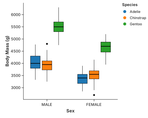
use charton::prelude::*;
use std::error::Error;

fn main() -> Result<(), Box<dyn Error>> {
    let ds = load_dataset("penguins")?;
    println!("{:?}", &ds);

    chart!(ds)?
        .mark_boxplot()?
        .encode((
            alt::x("Sex"),
            alt::y("Body Mass (g)"),
            alt::color("Species"),
        ))?
        .save("docs/src/images/grouped_boxplot.svg")?;

    Ok(())
}
mark_boxplot carries its own statistic, so no transform is needed: give it a
categorical x, a numeric y, and an optional color to group the boxes.
The composable quantile box
When you want the box as a layer rather than a finished chart,
transform_quantile_box emits just the inter-quartile box and the median as an
ordinary polygon. It uses the same lane layout as transform_band, so the box
always sits exactly over its violin.
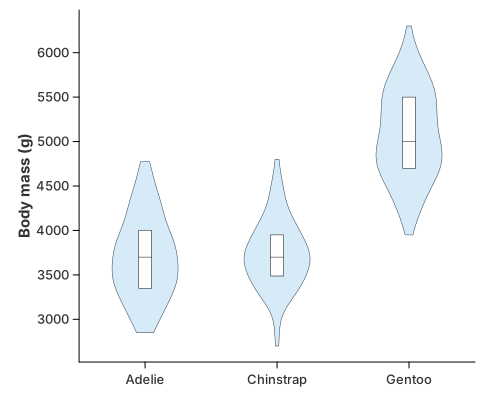
//! Violin with an inner box.
//!
//! The outline is `mark_violin`; the box is `transform_quantile_box`. They share
//! the same lane layout, so the box always sits exactly over its violin.

use charton::prelude::*;
use std::error::Error;

fn main() -> Result<(), Box<dyn Error>> {
    let penguins = load_dataset("penguins")?;

    let outline = chart!(&penguins)?
        .mark_violin()?
        .configure_violin(|mark| {
            mark.with_color("#d6eaf8")
                .with_opacity(1.0)
                .with_stroke("#2c3e50")
                .with_stroke_width(0.5)
        })
        .encode((alt::x("Species"), alt::y("Body Mass (g)")))?;

    let inner_box = chart!(&penguins)?
        .transform_quantile_box(
            QuantileBoxTransform::new("Body Mass (g)").with_category("Species"),
        )?
        .mark_polygon()?
        .configure_geoshape(|m| m.with_fill("white").with_stroke("black"))
        .encode((
            alt::x("x").with_category_labels("Species"),
            alt::y("y"),
            alt::path_group("path_group"),
        ))?;

    outline
        .and(inner_box)
        .with_x_label("")
        .with_y_label("Body mass (g)")
        .save("docs/src/images/violin_box.svg")?;

    println!("Saved docs/src/images/violin_box.svg");
    Ok(())
}
It emits a box_part column ("box" / "median") so the two polygons can be
styled differently, and copies the category / group columns back so the box
can be coloured and dodged like the outline it sits on.
Box on a violin
Because the box is just a layer, it stacks with .and(…) over any distribution
view — a plain violin, a dodged violin, or a full raincloud. See
Violin.
See also
- Violin — the outline form, and the raincloud that combines both.
- Transforms & Columns —
transform_quantile_boxcolumns.
Bars, Ranges & Comparisons
This page covers value comparisons: bars and error bars, and the range recipes
built on the same pieces — a dumbbell, a lollipop, a range plot, a waterfall and
a candlestick. They are all ordinary layers, so they share one set of scales and
compose with .and(…).
Basic Bar with Error Bars
Error bars are essential for communicating the precision of your data. This example shows the most common use case: a bar chart where each bar is accompanied by a vertical error bar calculated from pre-defined standard deviation values.
Key Concept: We use transform_calculate to dynamically create value_min and value_max columns within the chart pipeline.
use charton::prelude::*;
use std::error::Error;

fn main() -> Result<(), Box<dyn Error>> {
    // Create sample data with x and y values
    let type1 = ["a", "b", "c", "d"];
    let value = [4.9, 5.3, 5.5, 6.5];
    let value_std = [0.3, 0.39, 0.34, 0.20];

    // Create error bar chart using transform_calculate to add min/max values
    let errorbar = chart!(type1, value, value_std)?
        // Use transform_calculate to create ymin and ymax columns based on fixed std values
        .transform_calculate("value_min", |row| {
            Some(row.val("value")? - row.val("value_std")?)
        })?
        .transform_calculate("value_max", |row| {
            Some(row.val("value")? + row.val("value_std")?)
        })?
        .mark_errorbar()?
        .encode((alt::x("type1"), alt::y("value_min"), alt::y2("value_max")))?;
    let bar = chart!(type1, value)?
        .mark_bar()?
        .encode((alt::x("type1"), alt::y("value")))?;

    // Create a layered chart and add the errorbar chart as a layer
    errorbar
        .and(bar)
        .with_y_label("value")
        .save("docs/src/images/bar_with_errorbar.svg")?;

    Ok(())
}
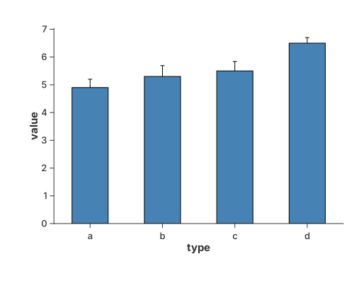
Grouped Bar with ErrorBar
When multiple groups are present (mapped to color), Charton automatically applies "dodge" logic to ensure that both the bars and the error bars are aligned side-by-side for each category.
use charton::prelude::*;
use std::error::Error;

fn main() -> Result<(), Box<dyn Error>> {
    let ds = load_dataset("penguins")?;
    println!("{:?}", ds);

    // 2. Build the Error Bar layer
    let errorbar = chart!(&ds)?
        .mark_errorbar()?
        // Mapping 'Sex' to color triggers the dodge logic
        .encode((
            alt::x("Species"),
            alt::y("Body Mass (g)"),
            alt::color("Sex"),
        ))?;

    // 3. Add a Bar layer to see the alignment
    let bar = chart!(ds)?.mark_bar()?.encode((
        alt::x("Species"),
        alt::y("Body Mass (g)").with_aggregate("mean"),
        alt::color("Sex"),
    ))?;

    // 4. Create the multiple layered Chart
    errorbar
        .and(bar)
        .with_size(600, 400)
        .with_title("Grouped Error Bars with Mean & Std Dev")
        .save("docs/src/images/grouped_bar_with_errorbar_1.svg")?;

    Ok(())
}
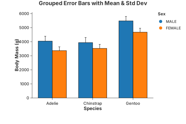
As an alternative approach, we demonstrate how to create a grouped error bar chart by manually defining the error boundaries using transform_calculate. While the previous one use automatic statistical aggregations, this method shows that the data generated through Charton's internal transformation pipeline is fully compatible across different layers. By calculating value_min and value_max within the errorbar layer, we ensure that the resulting dataset structure remains consistent with the mark_bar layer.
use charton::prelude::*;
use std::error::Error;

fn main() -> Result<(), Box<dyn Error>> {
    // Create sample data with x and y values
    let type1 = ["a", "a", "a", "a", "b", "b", "b", "b", "c", "c", "c", "c"];
    let value = [4.1, 5.3, 5.5, 6.5, 4.2, 5.1, 5.7, 5.5, 4.3, 5.5, 5.1, 6.8];
    let value_std = [
        0.22, 0.26, 0.14, 0.23, 0.2, 0.23, 0.12, 0.25, 0.21, 0.20, 0.16, 0.25,
    ];
    let group = ["E", "F", "G", "H", "E", "F", "G", "H", "E", "F", "G", "H"];

    // Create error bar chart using transform_calculate to add min/max values
    let errorbar = chart!(type1, value, value_std, group)?
        // Use transform_calculate to create ymin and ymax columns based on fixed std values
        .transform_calculate("value_min", |row| {
            Some(row.val("value")? - row.val("value_std")?)
        })?
        .transform_calculate("value_max", |row| {
            Some(row.val("value")? + row.val("value_std")?)
        })?
        .mark_errorbar()?
        .encode((
            alt::x("type1"),
            alt::y("value_min"),
            alt::y2("value_max"),
            alt::color("group"),
        ))?;

    // Create a bar chart
    let bar = chart!(type1, value, value_std, group)?
        .mark_bar()?
        .encode((alt::x("type1"), alt::y("value"), alt::color("group")))?;

    // Create a layered chart
    errorbar
        .and(bar)
        .save("docs/src/images/grouped_bar_with_errorbar_2.svg")?;

    Ok(())
}
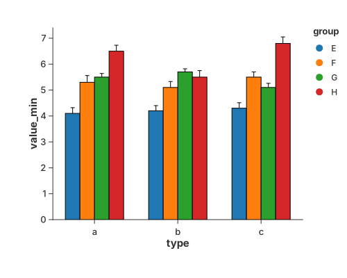
Stacked bar
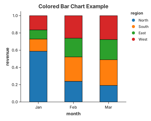
Segments stacked by a colour group; stack: "stacked" (the default for a
grouped bar).
use charton::prelude::*;
use std::error::Error;

fn main() -> Result<(), Box<dyn Error>> {
    let month = [
        "Jan", "Jan", "Jan", "Jan", "Feb", "Feb", "Feb", "Feb", "Mar", "Mar", "Mar", "Mar",
    ];
    let revenue = [
        500.0, 120.1, 90.0, 140.0, 110.0, 130.0, 100.0, 120.0, 90.0, 140.0, 110.0, 130.0,
    ];
    let region = [
        "North", "South", "East", "West", "North", "South", "East", "West", "North", "South",
        "East", "West",
    ];

    // Create a bar chart with color encoding
    chart!(month, revenue, region)?
        .mark_bar()?
        .configure_bar(|b| {
            b.with_stroke("black")
                .with_stroke_width(1.0)
                .with_width(0.5)
        })
        .encode((
            alt::x("month"),
            alt::y("revenue").with_normalize(true).with_stack("stacked"),
            alt::color("region"),
        ))?
        .with_title("Colored Bar Chart Example")
        .save("docs/src/images/stacked_bar.svg")?;

    Ok(())
}
Error bar on its own
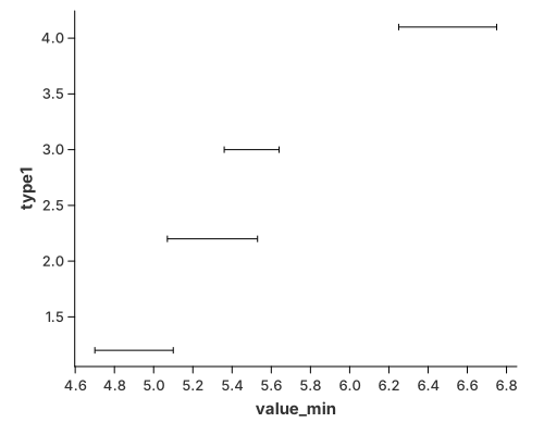
The interval geometry by itself, without a bar:
use charton::prelude::*;
use std::error::Error;

fn main() -> Result<(), Box<dyn Error>> {
    // Create sample data with x and y values
    let type1 = [1.2, 2.2, 3.0, 4.1];
    let value = [4.9, 5.3, 5.5, 6.5];
    let value_std = [0.2, 0.23, 0.14, 0.25];

    // Create error bar chart using transform_calculate to add min/max values
    chart!(type1, value, value_std)?
        // Use transform_calculate to create ymin and ymax columns based on fixed std values
        .transform_calculate("value_min", |row| {
            Some(row.val("value")? - row.val("value_std")?)
        })?
        .transform_calculate("value_max", |row| {
            Some(row.val("value")? + row.val("value_std")?)
        })?
        .mark_errorbar()?
        .encode((alt::x("type1"), alt::y("value_min"), alt::y2("value_max")))?
        .coord_flip()
        .save("docs/src/images/errorbar.svg")?;

    Ok(())
}
Dumbbell (connected dot)
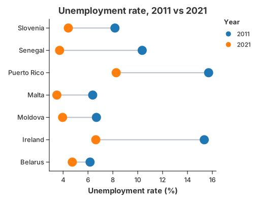
A dumbbell compares two values for each category — a before/after, an A/B, a min/max. Each row gets a dot at both values and a segment between them: the dot position shows the level, and the segment length shows how much changed.
It is a recipe, not a mark. mark_rule draws the connector from two wide columns
(y and y2); the dots come from a tidy table so the period can drive the
colour and produce a legend. coord_flip stands the categories up so the
segments run horizontally, and with_dodge(false) keeps the two ends on the
segment — a colour channel is otherwise a lane, which would push the periods
apart into two columns.
//! Dumbbell (connected dot) — two values per category, joined by a segment.
//!
//! A dumbbell is a recipe, not a mark. `mark_rule` draws the segment between the
//! two values and a `mark_point` layer marks each end; all layers share the
//! category and value scales, so they line up automatically. `coord_flip`
//! stands the categories up so the segments run horizontally.

use charton::prelude::*;
use std::error::Error;

fn main() -> Result<(), Box<dyn Error>> {
    // Unemployment rate (%), 2011 vs 2021, for seven countries.
    let country = [
        "Belarus",
        "Ireland",
        "Moldova",
        "Malta",
        "Puerto Rico",
        "Senegal",
        "Slovenia",
    ];
    let y2011 = [6.17, 15.35, 6.68, 6.38, 15.70, 10.36, 8.17];
    let y2021 = [4.74, 6.63, 3.96, 3.50, 8.27, 3.72, 4.42];

    // 1. The connector: one rule per country, from the 2011 value to the 2021
    //    value. The rule geometry reads `y` and `y2` from one wide row.
    let connector = chart!(country, y2011, y2021)?
        .mark_rule()?
        .configure_rule(|rule| rule.with_color("#b9bfc6").with_stroke_width(2.0))
        .encode((alt::x("country"), alt::y("y2011"), alt::y2("y2021")))?;

    // 2. The two ends: a tidy (long) table, one row per country and period, so
    //    the period can drive the colour and produce a legend.
    let countries_long: Vec<&str> = country.iter().chain(country.iter()).copied().collect();
    let periods: Vec<&str> = std::iter::repeat("2011")
        .take(7)
        .chain(std::iter::repeat("2021").take(7))
        .collect();
    let values: Vec<f64> = y2011.iter().chain(y2021.iter()).copied().collect();

    let ends = Dataset::new()
        .with_column("country", countries_long)?
        .with_column("period", periods)?
        .with_column("value", values)?;

    connector
        .and(
            chart!(&ends)?
                .mark_point()?
                // `with_dodge(false)` keeps both ends on the shared segment: a
                // colour channel is otherwise a *lane*, which would push the
                // two periods apart.
                .configure_point(|point| point.with_size(9.0).with_dodge(false))
                .encode((alt::x("country"), alt::y("value"), alt::color("period")))?,
        )
        .coord_flip()
        .with_title("Unemployment rate, 2011 vs 2021")
        .with_x_label("")
        .with_y_label("Unemployment rate (%)")
        .with_color_label("Year")
        .save("docs/src/images/dumbbell.svg")?;

    println!("Saved docs/src/images/dumbbell.svg");
    Ok(())
}
Lollipop and range
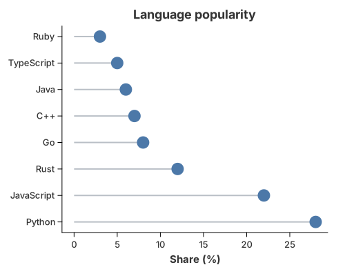
A bar with the fill thrown away: mark_rule draws the stem and mark_point
caps it. A range plot is the same rule with both ends away from the
baseline, and the dumbbell above is a range plot with two dots.
//! Lollipop — a bar with the fill thrown away.
//!
//! A recipe: `mark_rule` draws a thin stem from the baseline to each value and
//! `mark_point` caps it. Two ordinary geometries, no new mark. A *range plot*
//! is the same idea with both ends off the baseline (`y` to `y2`).

use charton::prelude::*;
use std::error::Error;

fn main() -> Result<(), Box<dyn Error>> {
    let language = [
        "Python",
        "JavaScript",
        "Rust",
        "Go",
        "C++",
        "Java",
        "TypeScript",
        "Ruby",
    ];
    let share = [28.0, 22.0, 12.0, 8.0, 7.0, 6.0, 5.0, 3.0];
    let base = [0.0; 8];

    let stems = chart!(language, share, base)?
        .mark_rule()?
        .configure_rule(|rule| rule.with_color("#b9bfc6").with_stroke_width(2.0))
        .encode((alt::x("language"), alt::y("base"), alt::y2("share")))?;

    let caps = chart!(language, share)?
        .mark_point()?
        .configure_point(|point| point.with_color("#4c78a8").with_size(9.0))
        .encode((alt::x("language"), alt::y("share")))?;

    stems
        .and(caps)
        .coord_flip()
        .with_title("Language popularity")
        .with_x_label("")
        .with_y_label("Share (%)")
        .save("docs/src/images/lollipop.svg")?;

    println!("Saved docs/src/images/lollipop.svg");
    Ok(())
}
Waterfall
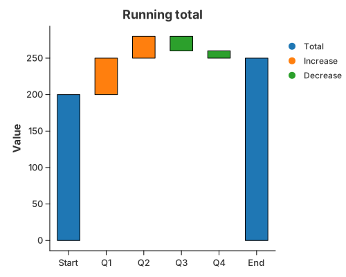
A running total as floating bars. transform_window with
WindowOnlyOp::CumulativeSum carries the total, and a y2 bound floats each
bar between the total before and after its step; colour splits increases
from decreases.
//! Waterfall — a running total shown as floating bars.
//!
//! Two public primitives do the work: `transform_window` with
//! `WindowOnlyOp::CumulativeSum` carries the running total, and `mark_bar` with
//! a `y2` bound draws each step as a bar that floats between the total *before*
//! and *after* it. The opening and closing **totals** are the same idea anchored
//! at zero (`base = 0`), so the picture needs one geometry, not two.

use charton::prelude::*;
use std::error::Error;

fn main() -> Result<(), Box<dyn Error>> {
    // Opening total, quarterly contributions, closing total.
    let step = ["Start", "Q1", "Q2", "Q3", "Q4", "End"];
    let delta = [200.0, 50.0, 30.0, -20.0, -10.0, 0.0];
    let kind = [
        "Total", "Increase", "Increase", "Decrease", "Decrease", "Total",
    ];

    chart!(step, delta, kind)?
        // The running total after each step ...
        .transform_window(WindowTransform::new(WindowFieldDef::new(
            "delta",
            WindowOnlyOp::CumulativeSum,
            "total",
        )))?
        // ... and the bar's lower edge: the total before the step, or zero for
        // the opening/closing total columns.
        .transform_calculate("base", |row| {
            if row.str("kind").as_deref() == Some("Total") {
                Some(0.0)
            } else {
                Some(row.val("total")? - row.val("delta")?)
            }
        })?
        .mark_bar()?
        .configure_bar(|bar| bar.with_width(0.6))
        .encode((
            alt::x("step"),
            alt::y("base"),
            alt::y2("total"),
            alt::color("kind"),
        ))?
        .with_title("Running total")
        .with_x_label("")
        .with_y_label("Value")
        .with_color_label("")
        .save("docs/src/images/waterfall.svg")?;

    println!("Saved docs/src/images/waterfall.svg");
    Ok(())
}
Candlestick
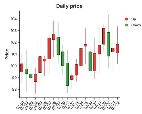
OHLC bars: mark_rule draws the high–low wick and a floating mark_bar (its
y2 bound) draws the open–close body, coloured by direction.
//! Candlestick — an OHLC bar per period.
//!
//! A recipe: `mark_rule` draws the high–low wick (`y` to `y2`) and `mark_bar`
//! with a `y2` bound draws the open–close body as a *floating* bar. Colour tells
//! an up day from a down day. The two layers share the category axis, so the
//! bodies sit exactly on their wicks.
//!
//! The prices are a seeded random walk, so the figure looks like a real price
//! series while still rendering identically every run.

use charton::prelude::*;
use std::error::Error;

fn main() -> Result<(), Box<dyn Error>> {
    // A tiny seeded LCG: deterministic, but with the run of a random walk.
    let mut seed: u64 = 0x9E37_79B9_7F4A_7C15;
    let mut noise = || {
        seed = seed
            .wrapping_mul(6364136223846793005)
            .wrapping_add(1442695040888963407);
        (seed >> 11) as f64 / (1u64 << 53) as f64 * 2.0 - 1.0
    };

    let days = 22;
    let mut open = Vec::with_capacity(days);
    let mut high = Vec::with_capacity(days);
    let mut low = Vec::with_capacity(days);
    let mut close = Vec::with_capacity(days);
    let round = |v: f64| (v * 100.0).round() / 100.0;
    let mut price = 100.0;

    for _ in 0..days {
        let o = price + noise() * 0.8; // gap from the previous close
        let c = o + noise() * 2.0 + (100.0 - o) * 0.08; // move, pulled toward 100
        let h = o.max(c) + noise().abs() * 1.5 + 0.2;
        let l = o.min(c) - noise().abs() * 1.5 - 0.2;
        open.push(round(o));
        close.push(round(c));
        high.push(round(h));
        low.push(round(l));
        price = c;
    }

    let day: Vec<String> = (1..=days).map(|d| format!("07-{d:02}")).collect();
    let direction: Vec<&str> = open
        .iter()
        .zip(close.iter())
        .map(|(o, c)| if c >= o { "Up" } else { "Down" })
        .collect();

    // A floating bar (a `y2` bound) does not force a zero baseline, so the price
    // axis stays on the traded range and the candles fill the panel.
    let wick = chart!(day, low, high, direction)?
        .mark_rule()?
        .configure_rule(|rule| rule.with_stroke_width(1.0))
        .encode((
            alt::x("day"),
            alt::y("low"),
            alt::y2("high"),
            alt::color("direction"),
        ))?;

    let body = chart!(day, open, close, direction)?
        .mark_bar()?
        .configure_bar(|bar| bar.with_width(0.6))
        .encode((
            alt::x("day"),
            alt::y("open"),
            alt::y2("close"),
            alt::color("direction"),
        ))?;

    wick.and(body)
        .configure_theme(|theme| {
            // Chinese-market convention: red for an up day, green for a down day.
            theme
                .with_palette(ColorPalette::from(vec!["#e53935", "#43a047"]))
                .with_x_tick_label_angle(-45.0)
        })
        .with_title("Daily price")
        .with_x_label("")
        .with_y_label("Price")
        .with_color_label("")
        .save("docs/src/images/candlestick.svg")?;

    println!("Saved docs/src/images/candlestick.svg");
    Ok(())
}
Line Charts
A line connects the rows of a group in x-order. One group per colour, so a
multi-series line is just color.
Multiple series
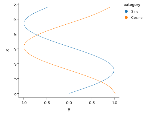
Two curves on one axis. configure_line also offers smoothing (LOESS) when the
data is noisy.
use charton::prelude::*;

fn main() -> Result<(), Box<dyn std::error::Error>> {
    // Create data for multiple groups (e.g., sine and cosine curves)
    let x_values: Vec<f64> = (0..30).map(|i| i as f64 * 0.2).collect();
    let y_sine: Vec<f64> = x_values.iter().map(|&x| x.sin()).collect();
    let y_cosine: Vec<f64> = x_values.iter().map(|&x| x.cos()).collect();

    // Combine data into a single DataFrame with categories
    let x = x_values.repeat(2); // Repeat x values for both groups
    let y = [y_sine.clone(), y_cosine.clone()].concat();
    let category = [vec!["Sine"; 30], vec!["Cosine"; 30]].concat();

    // Create a line chart with multiple groups
    chart!(x, y, category)?
        .mark_line()?
        .configure_line(|l| l.with_loess(true).with_loess_bandwidth(0.2))
        .encode((
            alt::x("x"),
            alt::y("y"),
            alt::color("category"), // This creates separate lines for each category
        ))?
        .configure_theme(|t| t.with_x_tick_label_angle(-45.0))
        .coord_flip()
        .save("docs/src/images/line.svg")?;

    Ok(())
}
Gaps
A missing x or y breaks the line instead of drawing across it, so an outage
in a time series reads as a gap in the curve. See
Missing Values & Gaps.
Cumulative frequency
A running total as a line — the cumulative shape of a distribution without a histogram.
use charton::prelude::*;
use std::error::Error;

fn main() -> Result<(), Box<dyn Error>> {
    let ds = load_dataset("iris")?;
    // Create a chart with window transform
    chart!(ds)?
        .transform_window(
            WindowTransform::new(WindowFieldDef::new(
                "sepal_length",
                WindowOnlyOp::CumeDist,
                "ecdf", // This will be the output column name
            ))
            .with_groupbys(["species"])
            .with_normalize(false),
        )?
        .mark_line()?
        .configure_line(|l| l.with_interpolation("step")) // Add step interpolation
        .encode((
            alt::x("sepal_length"),
            alt::y("ecdf"),
            alt::color("species"),
        ))?
        .with_title("Empirical Cumulative Distribution")
        .save("docs/src/images/cumulative_frequency.svg")?;

    Ok(())
}
Multi-series with error bars
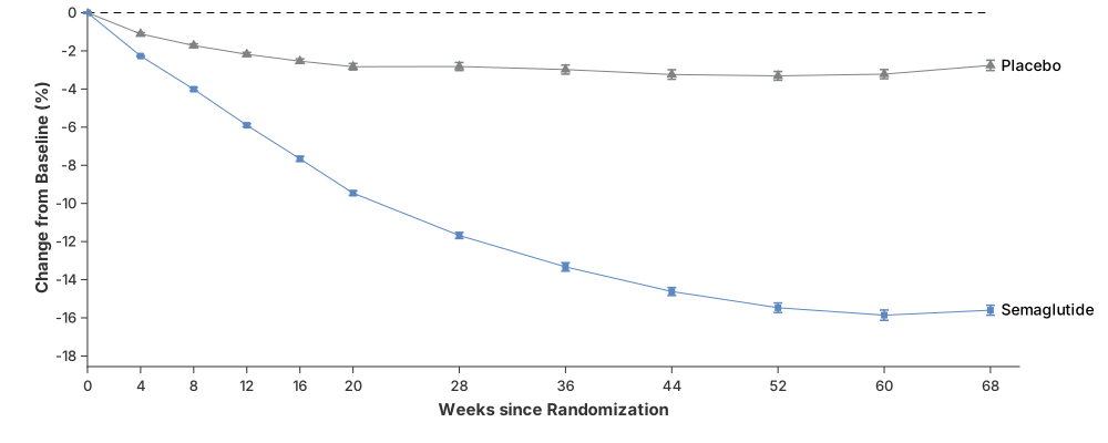
Lines plus mark_errorbar and points, layered with .and(…) — the shape of a
published trial figure.
use charton::prelude::*;
use std::error::Error;

// The data is obtained from paper "Once-Weekly Semaglutide in Adults with Overweight or Obesity"
// using [webplotdigitizer](https://automeris.io/).
fn main() -> Result<(), Box<dyn Error>> {
    // Placebo group data (control group)
    let ds_placebo = vec![
        // X-axis: time since randomization (weeks)
        (
            "Weeks since Randomization",
            [0, 4, 8, 12, 16, 20, 28, 36, 44, 52, 60, 68].into_column(),
        ),
        // Y-axis: mean percentage change in body weight from baseline. Negative values indicate weight loss
        (
            "Change from Baseline (%)",
            [
                0.00, -1.11, -1.72, -2.18, -2.54, -2.83, -2.82, -2.98, -3.24, -3.31, -3.22, -2.76,
            ]
            .into_column(),
        ),
        // Lower bound of the confidence interval (typically 95% CI)
        (
            "lower",
            [
                -0.042, -1.18, -1.81, -2.28, -2.66, -3.00, -3.03, -3.22, -3.49, -3.54, -3.46, -3.03,
            ]
            .into_column(),
        ),
        // Upper bound of the confidence interval (95% CI)
        (
            "upper",
            [
                0.042, -1.04, -1.63, -2.08, -2.42, -2.66, -2.61, -2.74, -2.99, -3.08, -2.98, -2.49,
            ]
            .into_column(),
        ),
    ]
    .to_dataset()?;

    // Semaglutide group data (treatment group)
    let ds_semaglutide = vec![
        (
            "Weeks since Randomization",
            [0, 4, 8, 12, 16, 20, 28, 36, 44, 52, 60, 68].into_column(),
        ),
        (
            "Change from Baseline (%)",
            [
                0.00, -2.27, -4.01, -5.9, -7.66, -9.46, -11.68, -13.33, -14.62, -15.47, -15.86,
                -15.6,
            ]
            .into_column(),
        ),
        (
            "lower",
            [
                -0.041, -2.3, -4.1, -5.98, -7.79, -9.58, -11.84, -13.55, -14.83, -15.72, -16.13,
                -15.86,
            ]
            .into_column(),
        ),
        (
            "upper",
            [
                0.041, -2.24, -3.92, -5.82, -7.53, -9.34, -11.52, -13.11, -14.41, -15.22, -15.59,
                -15.34,
            ]
            .into_column(),
        ),
    ]
    .to_dataset()?;

    // Text labels (placed at the right side of the plot)
    let ds_text = vec![
        ("x", [68.8, 68.8].into_column()),
        ("y", [-3.05, -15.86].into_column()),
        ("group", ["Placebo", "Semaglutide"].into_column()),
    ]
    .to_dataset()?;

    // Reference line (y = 0 → no weight change)
    let ds_reference = vec![
        ("x", [0.0, 76.0].into_column()),
        ("y", [0.0, 0.0].into_column()),
    ]
    .to_dataset()?;

    // Layer 1: Placebo points (markers at each time point)
    let placebo_point = Chart::build(&ds_placebo)?
        .mark_point()?
        .configure_point(|p| {
            p.with_color("#818284")
                .with_shape("triangle")
                .with_size(5.0)
        })
        .encode((
            alt::x("Weeks since Randomization"),
            alt::y("Change from Baseline (%)"),
        ))?;

    // Layer 2: Placebo line (connects the points)
    let placebo_line = Chart::build(&ds_placebo)?
        .mark_line()?
        .configure_line(|l| l.with_color("#818284"))
        .encode((
            alt::x("Weeks since Randomization"),
            alt::y("Change from Baseline (%)"),
        ))?;

    // Layer 3: Placebo error bars (confidence intervals)
    let placebo_errorbar = Chart::build(&ds_placebo)?
        .mark_errorbar()?
        .configure_errorbar(|e| {
            e.with_color("#818284")
                .with_cap_length(4.0)
                .with_stroke_width(1.5)
        })
        .encode((
            alt::x("Weeks since Randomization"),
            alt::y("lower"),
            alt::y2("upper"),
        ))?;

    // Layer 4: Placebo text label
    let placebo_text = Chart::build(ds_text.head(1))?
        .mark_text()?
        .configure_text(|t| t.with_anchor("left").with_size(14.0))
        .encode((alt::x("x"), alt::y("y"), alt::text("group")))?;

    // Layer 5: Semaglutide points
    let semaglutide_point = Chart::build(&ds_semaglutide)?
        .mark_point()?
        .configure_point(|p| p.with_color("#5b88c3").with_shape("square").with_size(3.0))
        .encode((
            alt::x("Weeks since Randomization"),
            alt::y("Change from Baseline (%)"),
        ))?;

    // Layer 6: Semaglutide line
    let semaglutide_line = Chart::build(&ds_semaglutide)?
        .mark_line()?
        .configure_line(|l| l.with_color("#5b88c3"))
        .encode((
            alt::x("Weeks since Randomization"),
            alt::y("Change from Baseline (%)"),
        ))?;

    // Layer 7: Semaglutide error bars
    let semaglutide_errorbar = Chart::build(&ds_semaglutide)?
        .mark_errorbar()?
        .configure_errorbar(|e| {
            e.with_color("#5b88c3")
                .with_cap_length(4.0)
                .with_stroke_width(1.5)
        })
        .encode((
            alt::x("Weeks since Randomization"),
            alt::y("lower"),
            alt::y2("upper"),
        ))?;

    // Layer 8: Semaglutide text label
    let semaglutide_text = Chart::build(ds_text.tail(1))?
        .mark_text()?
        .configure_text(|t| t.with_anchor("left").with_size(14.0))
        .encode((alt::x("x"), alt::y("y"), alt::text("group")))?;

    // Layer 9: Reference line (baseline at 0%)
    let reference_line = Chart::build(&ds_reference)?
        .mark_line()?
        .configure_line(|l| l.with_dash([6.0, 6.0]))
        .encode((alt::x("x"), alt::y("y")))?;

    // Combine all layers (Grammar of Graphics composition)
    placebo_point
        .and(reference_line)
        .and(placebo_line)
        .and(placebo_errorbar)
        .and(placebo_text)
        .and(semaglutide_point)
        .and(semaglutide_line)
        .and(semaglutide_errorbar)
        .and(semaglutide_text)
        .with_x_expand(Expansion {
            mult: (0.00, 0.0),
            add: (0.0, 0.0),
        })
        .with_y_expand(Expansion {
            mult: (0.15, 0.01),
            add: (0.0, 0.0),
        })
        .with_size(1000, 400)
        .with_right_margin(0.08)
        .with_left_margin(0.02)
        .with_top_margin(0.02)
        .with_bottom_margin(0.03)
        .with_x_ticks([
            0.0, 4.0, 8.0, 12.0, 16.0, 20.0, 28.0, 36.0, 44.0, 52.0, 60.0, 68.0,
        ])
        .with_y_ticks([
            0.0, -2.0, -4.0, -6.0, -8.0, -10.0, -12.0, -14.0, -16.0, -18.0,
        ])
        .save("docs/src/images/weight_loss_curve.svg")?;

    Ok(())
}
Formatted axis labels (Economist style)

Axis labels are a scale concern: with_y_label_format(...) renders large values
as $20B instead of raw numbers.
//! Production-style label formatting.
//!
//! Reproduces the scenario from the issue: an "Economist-style" investment
//! chart where the y axis shows large values as `$20B` instead of raw numbers,
//! and the legend labels are tidied up.
//!
//! Run with: `cargo run --example label_format`

use charton::core::guide::LegendPosition;
use charton::prelude::*;

fn main() -> Result<(), Box<dyn std::error::Error>> {
    // Three focus areas, eight years, values in dollars.
    let years: Vec<f64> = (2015..2023).map(|year| year as f64).collect();
    let areas = [
        "Medical and healthcare",
        "Data management, processing, cloud",
        "Retail",
    ];

    let mut x = Vec::new();
    let mut investment = Vec::new();
    let mut area = Vec::new();
    for (index, name) in areas.iter().enumerate() {
        for year in &years {
            x.push(*year);
            // A made-up exponential-ish growth curve per area.
            let base = 2.0e9 * (index as f64 + 1.0);
            investment.push(base * (1.0 + (year - 2015.0) * 0.45).powf(1.8));
            area.push(*name);
        }
    }

    // Dollars, abbreviated, no decimals: 20_000_000_000 -> "$20B".
    let money = LabelFormat::new()
        .with_prefix("$")
        .with_compact_notation()
        .with_precision(0);

    // Legend labels: turn the long data names into short, readable ones.
    let short_names = LabelFormat::new().with_text_formatter(|label| match label {
        "Medical and healthcare" => "Healthcare".to_string(),
        "Data management, processing, cloud" => "Data & cloud".to_string(),
        other => other.to_string(),
    });

    chart!(x, investment, area)?
        .mark_line()?
        .encode((alt::x("x"), alt::y("investment"), alt::color("area")))?
        .with_size(760, 460)
        .with_x_label("Year")
        .with_y_label("")
        .with_color_label("Focus area")
        .with_y_label_format(money)
        .with_legend_label_format(short_names)
        .configure_theme(|theme| theme.with_legend_position(LegendPosition::Top))
        .save("docs/src/images/label_format.svg")?;

    Ok(())
}
Slope chart
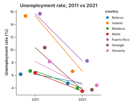
Change between two points in time: mark_line connects each group's two values
and mark_point marks them. Grouping the line is just color.
//! Slope chart — change between two points in time.
//!
//! A recipe: `mark_line` connects each country's two values across the two
//! periods and `mark_point` marks them. Grouping the line by colour is all it
//! takes; the two layers share the category and value scales.

use charton::prelude::*;
use std::error::Error;

fn main() -> Result<(), Box<dyn Error>> {
    let country = [
        "Belarus",
        "Ireland",
        "Moldova",
        "Malta",
        "Puerto Rico",
        "Senegal",
        "Slovenia",
    ];
    let y2011 = [6.17, 15.35, 6.68, 6.38, 15.70, 10.36, 8.17];
    let y2021 = [4.74, 6.63, 3.96, 3.50, 8.27, 3.72, 4.42];

    let countries_long: Vec<&str> = country.iter().chain(country.iter()).copied().collect();
    let periods: Vec<&str> = std::iter::repeat("2011")
        .take(7)
        .chain(std::iter::repeat("2021").take(7))
        .collect();
    let values: Vec<f64> = y2011.iter().chain(y2021.iter()).copied().collect();

    let ds = Dataset::new()
        .with_column("country", countries_long)?
        .with_column("period", periods)?
        .with_column("rate", values)?;

    let lines = chart!(&ds)?
        .mark_line()?
        .configure_line(|line| line.with_stroke_width(2.0))
        .encode((alt::x("period"), alt::y("rate"), alt::color("country")))?;

    let dots = chart!(&ds)?
        .mark_point()?
        .configure_point(|point| point.with_size(7.0))
        .encode((alt::x("period"), alt::y("rate"), alt::color("country")))?;

    lines
        .and(dots)
        .with_title("Unemployment rate, 2011 vs 2021")
        .with_x_label("")
        .with_y_label("Unemployment rate (%)")
        .save("docs/src/images/slope.svg")?;

    println!("Saved docs/src/images/slope.svg");
    Ok(())
}
Bump chart
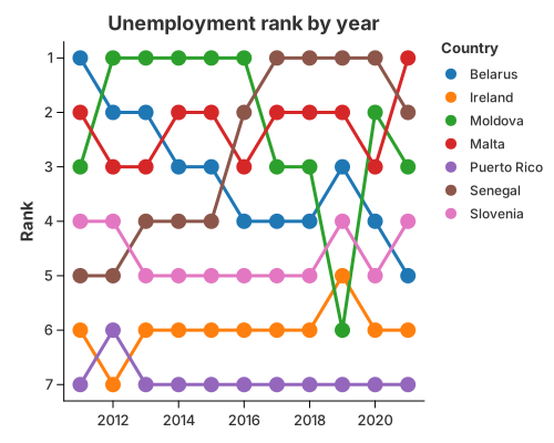
How a ranking moves over time. transform_window with WindowOnlyOp::Rank
ranks each group inside every period, and ordinary line/point layers draw the
trajectories. The y-axis is reversed with with_reverse(true) so rank 1 sits at
the top.
//! Bump chart — how a ranking changes over time.
//!
//! Ranks are a statistic, not a new geometry: `transform_window` with
//! `WindowOnlyOp::Rank` ranks each country inside every year, and ordinary
//! `mark_line`/`mark_point` layers draw the trajectories. The y-axis is
//! reversed (`with_reverse(true)`) so rank 1 sits at the top.

use charton::prelude::*;
use std::error::Error;

fn main() -> Result<(), Box<dyn Error>> {
    let unemployment = load_dataset("unemployment")?;
    let rank = || {
        WindowTransform::new(WindowFieldDef::new(
            "Unemployment rate (%)",
            WindowOnlyOp::Rank,
            "rank",
        ))
        .with_groupbys(["Year"])
    };

    let lines = chart!(&unemployment)?
        .transform_window(rank())?
        .mark_line()?
        .configure_line(|line| line.with_stroke_width(3.0))
        .encode((
            alt::x("Year"),
            alt::y("rank").with_reverse(true),
            alt::color("Country"),
        ))?;

    let dots = chart!(&unemployment)?
        .transform_window(rank())?
        .mark_point()?
        .configure_point(|point| point.with_size(7.0))
        .encode((
            alt::x("Year"),
            alt::y("rank").with_reverse(true),
            alt::color("Country"),
        ))?;

    lines
        .and(dots)
        .with_title("Unemployment rank by year")
        .with_x_label("")
        .with_y_label("Rank")
        .save("docs/src/images/bump.svg")?;

    println!("Saved docs/src/images/bump.svg");
    Ok(())
}
Area Charts
An area fills the region between a line and its baseline. Adding a colour field stacks the series; changing the stack baseline yields the streamgraph.
Area chart
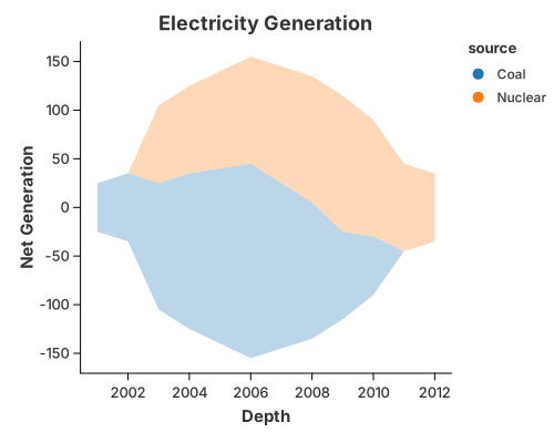
use charton::prelude::*;
use std::error::Error;

fn main() -> Result<(), Box<dyn Error>> {
    // Create sample data similar to the Iowa electricity dataset
    let depth = vec![
        2001, 2002, 2003, 2004, 2005, 2006, 2007, 2008, 2009, 2010, 2003, 2004, 2005, 2006, 2007,
        2008, 2009, 2010, 2011, 2012,
    ];
    let net_generation = vec![
        50.0, 70.0, 130.0, 160.0, 180.0, 200.0, 170.0, 140.0, 90.0, 60.0, 80.0, 90.0, 100.0, 110.0,
        120.0, 130.0, 140.0, 120.0, 90.0, 70.0,
    ];
    let source = vec![
        "Coal", "Coal", "Coal", "Coal", "Coal", "Coal", "Coal", "Coal", "Coal", "Coal", "Nuclear",
        "Nuclear", "Nuclear", "Nuclear", "Nuclear", "Nuclear", "Nuclear", "Nuclear", "Nuclear",
        "Nuclear",
    ];

    // Create an area chart
    let area_chart = chart!(depth, net_generation, source)?
        .mark_area()?
        .configure_area(|a| a.with_opacity(0.3).with_stroke("black"))
        .encode((
            alt::x("depth"),
            alt::y("net_generation").with_stack("center"),
            alt::color("source"),
        ))?;

    // Create a layered chart for the area
    area_chart
        .with_title("Electricity Generation")
        .with_x_label("Depth")
        .with_y_label("Net Generation")
        .save("docs/src/images/area.svg")?;

    Ok(())
}
Gaps
A missing x or y opens the area at that point instead of bridging it. See
Missing Values & Gaps.
Simple Stacked Area Chart
Adding a color field to area chart creates stacked area chart by default. For example, here we split the area chart by country by setting stack to "stacked".
use charton::prelude::*;
use std::error::Error;

fn main() -> Result<(), Box<dyn Error>> {
    // Create sample data similar to the Iowa electricity dataset
    let ds = load_dataset("unemployment")?;
    println!("{:?}", ds);
    // Create an area chart
    let area_chart = chart!(ds)?.mark_area()?.encode((
        alt::x("Year"),
        alt::y("Unemployment rate (%)").with_stack("stacked"),
        alt::color("Country"),
    ))?;

    // Create a layered chart for the area
    area_chart.save("docs/src/images/simple_stacked_area.svg")?;

    Ok(())
}
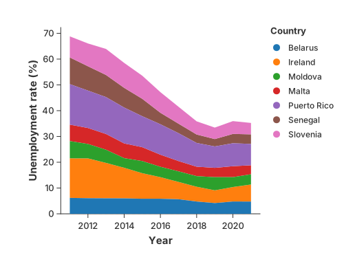
Normalized Stacked Area Chart
You can also create a normalized stacked area chart by setting stack to "normalize" in the encoding channel. Here we can easily see the percentage of unemployment across countries.
use charton::prelude::*;
use std::error::Error;

fn main() -> Result<(), Box<dyn Error>> {
    let ds = load_dataset("unemployment")?;
    println!("{:?}", ds.tail(5));
    let area_chart = chart!(ds)?.mark_area()?.encode((
        alt::x("Year"),
        alt::y("Unemployment rate (%)").with_stack("normalize"),
        alt::color("Country"),
    ))?;

    area_chart.save("docs/src/images/normalized_stacked_area.svg")?;

    Ok(())
}
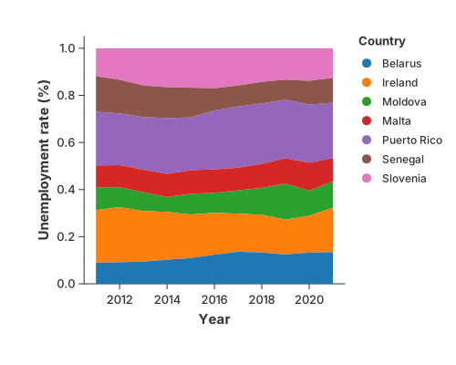
Steamgraph
We can also shift the stacked area chart’s baseline to center and produces a streamgraph by setting stack to "center" in the encoding channel.
use charton::prelude::*;
use std::error::Error;

fn main() -> Result<(), Box<dyn Error>> {
    let ds = load_dataset("unemployment")?;
    println!("{:?}", ds);
    let area_chart = Chart::build(&ds)?.mark_area()?.encode((
        alt::x("Year"),
        alt::y("Unemployment rate (%)").with_stack("center"),
        alt::color("Country"),
    ))?;

    area_chart.save("docs/src/images/steamgraph.svg")?;

    Ok(())
}
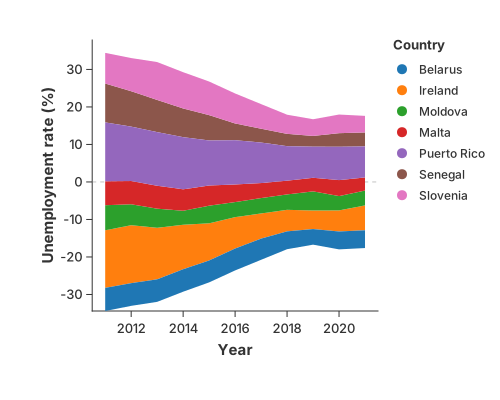
Scatter
mark_point is the base point geometry: shape, size and colour are ordinary
channels, and a layout can spread overlapping observations.
Shape, size and a reference grid
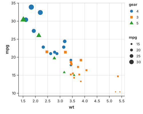
The grid is a theme feature (with_grid(true)), not a mark — turn it on for
any chart.
use charton::prelude::*;
use std::error::Error;

fn main() -> Result<(), Box<dyn Error>> {
    // Load the mtcars dataset
    let ds = load_dataset("mtcars")?;

    // Build a scatter plot
    Chart::build(ds)?
        .mark_point()?
        .configure_point(|p| p.with_size(30.0))
        .encode((
            alt::x("wt"),
            alt::y("mpg"),
            alt::color("gear").with_scale(Scale::Discrete),
            alt::shape("gear").with_scale(Scale::Discrete),
            alt::size("mpg"),
        ))?
        .with_grid(true)
        .save("docs/src/images/grid_line.svg")?;

    Ok(())
}
Point layouts
When points overlap — usually because one axis is categorical — a layout spreads them without changing their x position, so every observation stays visible:
- Jitter — small random offsets; good when you only need to break ties.
- Beeswarm — deterministic packing, so no two points overlap; best for small groups.
- Quasirandom — a low-discrepancy sequence that spreads points evenly and traces the outline of the distribution; best for large groups.
The layout is a property of the point mark:
#![allow(unused)]
fn main() {
.configure_point(|m| m.with_layout("beeswarm").with_size(1.5))
}
Separately from the layout, a color grouping dodges points into
side-by-side lanes — but only on a categorical x axis, where a lane means
something. On a continuous axis the points stay on their own x, so they line up
with a rule, line or area drawn through them. with_dodge(false) turns the lane
off even on a categorical axis, so the colour is an attribute rather than a
group (the dumbbell uses
it).
Beeswarm
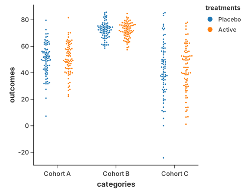
use charton::prelude::*;

fn main() -> Result<(), Box<dyn std::error::Error>> {
    let mut categories = Vec::new();
    let mut outcomes = Vec::new();
    let mut treatments = Vec::new();

    let configs = [
        ("Cohort A", 45.0, 12.0),
        ("Cohort B", 70.0, 6.0),
        ("Cohort C", 35.0, 18.0),
    ];

    let treatment_types = ["Placebo", "Active"];

    // Use a simple deterministic counter to simulate "randomness"
    let mut seed: u32 = 42;

    for (label, mean, std_dev) in configs {
        for i in 0..150 {
            categories.push(label.to_string());

            // 1. Deterministic Pseudo-random using LCG
            seed = seed.wrapping_mul(1103515245).wrapping_add(12345);
            let raw_rand = (seed & 0x7FFFFFFF) as f64 / 2147483647.0;

            // 2. Simple Box-Muller transform to simulate Normal Distribution
            // This creates the "cluster" effect needed to show off Beeswarm
            let u1 = raw_rand;
            let u2 = ((i as f64 * 0.1).sin() + 1.0) / 2.0; // Another "random" seed
            let z0 = (-2.0 * u1.ln().max(-10.0)).sqrt() * (2.0 * std::f64::consts::PI * u2).cos();

            outcomes.push(mean + z0 * std_dev);

            // 3. Deterministic sub-group assignment
            let sub_idx = (i % 2) as usize;
            treatments.push(treatment_types[sub_idx].to_string());
        }
    }

    // 2. Render the Chart
    chart!(categories, outcomes, treatments)?
        .mark_point()?
        .configure_point(|m| m.with_layout("beeswarm").with_size(1.5))
        .encode((
            alt::x("categories"),
            alt::y("outcomes"),
            alt::color("treatments"),
        ))?
        .save("docs/src/images/beeswarm.svg")?;

    Ok(())
}
Quasirandom
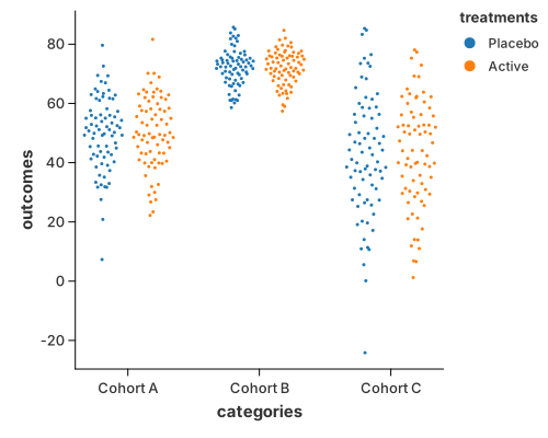
use charton::prelude::*;

fn main() -> Result<(), Box<dyn std::error::Error>> {
    let mut categories = Vec::new();
    let mut outcomes = Vec::new();
    let mut treatments = Vec::new();

    let configs = [
        ("Cohort A", 45.0, 12.0),
        ("Cohort B", 70.0, 6.0),
        ("Cohort C", 35.0, 18.0),
    ];

    let treatment_types = ["Placebo", "Active"];

    // Deterministic counter used to build a repeatable normal sample.
    let mut seed: u32 = 42;

    for (label, mean, std_dev) in configs {
        for i in 0..150 {
            categories.push(label.to_string());

            seed = seed.wrapping_mul(1103515245).wrapping_add(12345);
            let raw_rand = (seed & 0x7FFFFFFF) as f64 / 2147483647.0;

            let u1 = raw_rand;
            let u2 = ((i as f64 * 0.1).sin() + 1.0) / 2.0;
            let z0 = (-2.0 * u1.ln().max(-10.0)).sqrt() * (2.0 * std::f64::consts::PI * u2).cos();

            outcomes.push(mean + z0 * std_dev);

            let sub_idx = (i % 2) as usize;
            treatments.push(treatment_types[sub_idx].to_string());
        }
    }

    // The default method spreads the cloud with a low discrepancy sequence,
    // which gives the smooth violin outline.
    chart!(categories, outcomes, treatments)?
        .mark_point()?
        .configure_point(|m| m.with_layout("quasirandom").with_size(1.5))
        .encode((
            alt::x("categories"),
            alt::y("outcomes"),
            alt::color("treatments"),
        ))?
        .save("docs/src/images/quasirandom.svg")?;

    // The pseudorandom method keeps the density scaling but pairs the points
    // with a random-like sequence, so the outline is noisier.
    chart!(categories, outcomes, treatments)?
        .mark_point()?
        .configure_point(|m| {
            m.with_layout("quasirandom")
                .with_quasirandom_method("pseudorandom")
                .with_size(1.5)
        })
        .encode((
            alt::x("categories"),
            alt::y("outcomes"),
            alt::color("treatments"),
        ))?
        .save("target/example-output/quasirandom_pseudorandom.svg")?;

    Ok(())
}
The quasirandom pairing can be changed with
with_quasirandom_method("pseudorandom").
A strip / rug plot is the same idea with mark_tick instead of mark_point:
see Strip & Rug Plots.
See also
- Marks & Geometries — the point mark and its layouts.
- Histogram and 1-D Density — the summarised views of the same observations.
Strip & Rug Plots
A tick is a short line; many ticks along an axis read as density.
Strip Plot
The following example uses tick marks to show the distribution of sepal width in the Iris dataset. By adding a y field (categorical data), a strip plot is created to show the distribution of sepal width across different species.
use charton::prelude::*;
use std::error::Error;

fn main() -> Result<(), Box<dyn Error>> {
    let ds = load_dataset("iris")?;

    let chart = Chart::build(&ds)?.mark_tick()?.encode((
        alt::x("sepal_width"),
        alt::y("species"),
        alt::color("species"),
    ))?;

    chart.save("docs/src/images/strip.svg")?;

    Ok(())
}
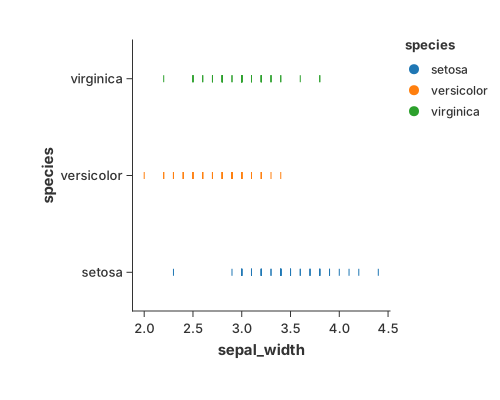
When there only one category or color encoding is absent, it degeneates to a "rug" of lines along the bottom.
You can precisely control the visual weight of the ticks using configure_tick. This is useful for balancing the "density" look of the chart.
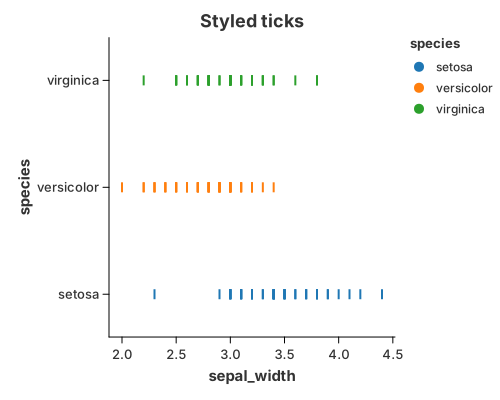
//! Styling ticks.
//!
//! `configure_tick` controls the visual weight of the marks: thickness, band
//! size and colour. This is useful for balancing a dense strip plot.

use charton::prelude::*;
use std::error::Error;

fn main() -> Result<(), Box<dyn Error>> {
    let ds = load_dataset("iris")?;

    Chart::build(&ds)?
        .mark_tick()?
        .configure_tick(|m| {
            m.with_thickness(2.0)
                .with_band_size(10.0)
                .with_color("blue")
        })
        .encode((
            alt::x("sepal_width"),
            alt::y("species"),
            alt::color("species"),
        ))?
        .with_title("Styled ticks")
        .save("docs/src/images/tick_style.svg")?;

    println!("Saved docs/src/images/tick_style.svg");
    Ok(())
}
Significance and Usage
-
Significance: Unlike a
point, atickemphasizes positional density. Because of its linear shape, overlapping ticks create a "barcode" effect that intuitively reveals where data points are most concentrated. -
Common Use Cases:
- Rug Plots: Often placed at the edges of scatter plots or histograms to show marginal distributions.
- Strip Plots: Used as an alternative to box plots when the dataset is small to medium-sized, allowing every individual data point to be seen.
- High-Performance Rendering: In Rust-based engines like
charton, rendering simple quads (ticks) is extremely efficient for visualizing millions of data points compared to complex shapes.
Heatmaps
A heatmap is mark_rect over two position axes, coloured by a value. The only
question is whether the axes are categorical or continuous.
Categorical heatmap
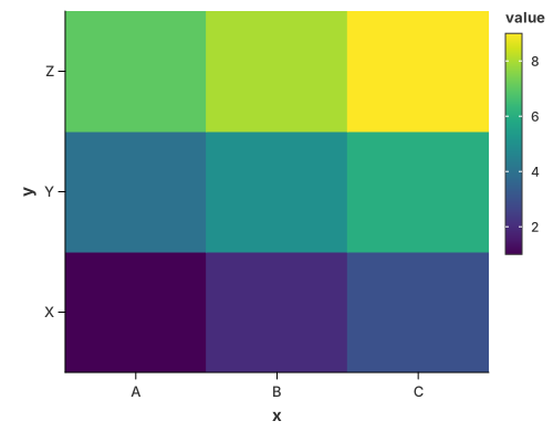
Each (x, y) pair is one cell, coloured by its value.
//! Heatmap over two **categorical** axes.
//!
//! Each `(x, y)` pair is one cell, coloured by its value. Continuous axes use
//! the same mark with automatic binning — see `heatmap_rect.rs`.

use charton::prelude::*;
use std::error::Error;

fn main() -> Result<(), Box<dyn Error>> {
    // Sample data for heatmap
    let x = ["A", "B", "C", "A", "B", "C", "A", "B", "C"];
    let y = ["X", "X", "X", "Y", "Y", "Y", "Z", "Z", "Z"];
    let value = [1.0, 2.0, 3.0, 4.0, 5.0, 6.0, 7.0, 8.0, 9.0];

    // Create heatmap chart
    chart!(x, y, value)?
        .mark_rect()?
        .encode((alt::x("x"), alt::y("y"), alt::color("value")))?
        .save("docs/src/images/heatmap.svg")?;

    Ok(())
}
Continuous heatmap (2-D binning)
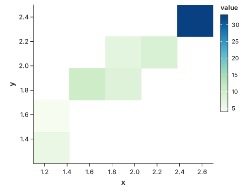
The same mark with automatic binning on both axes — a "2-D histogram" heatmap.
//! Heatmap over two **continuous** columns.
//!
//! `mark_rect` slices the x and y axes into a grid and paints each cell with the
//! colour of the value that falls in it. This is the "2D density heatmap" shape;
//! for the iso-lines of a density instead, see `density_contour.rs`.

use charton::prelude::*;
use std::error::Error;

fn main() -> Result<(), Box<dyn Error>> {
    // Sample data for heatmap with continuous variables
    let x = [1.1, 1.2, 1.3, 1.4, 1.5, 1.6, 1.8, 2.05, 2.2, 2.5, 2.6, 2.7];
    let y = [1.2, 1.3, 1.4, 1.5, 1.8, 1.83, 2.0, 1.9, 2.2, 2.3, 2.4, 2.5];
    let value = [
        1.0, 2.0, 3.0, 4.0, 5.0, 6.0, 7.0, 8.0, 9.0, 10.0, 11.0, 12.0,
    ];
    // Create heatmap chart
    chart!(x, y, value)?
        .mark_rect()?
        .encode((alt::x("x"), alt::y("y"), alt::color("value")))?
        .configure_theme(|t| t.with_color_map(ColorMap::GnBu))
        .save("docs/src/images/heatmap_rect.svg")?;

    Ok(())
}
See also
- Contour Plots — the smooth, iso-line alternative to a binned heatmap, including density contours.
Contour Plots
A contour plot draws the lines (or bands) where a scalar field equals a set of levels.
mark_contour is the convenient way to draw one. It is a composite mark:
behind the scenes it expands into the ordinary recipe
contour = iso-line stat (marching squares) + open-path geometry
so the general pieces stay available. transform_contour works on any regular
grid of x, y and z — an elevation map, a pressure field, a bivariate
density — and mark_path draws any ordered polyline.
Iso-lines of a grid
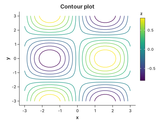
Name the scalar field explicitly (the crate has no z channel) and read x/y
from the encodings. The lines are coloured by their level by default.
//! Contour plot — the convenience `mark_contour`.
//!
//! `mark_contour` is a **composite** mark: it expands into the public
//! `transform_contour` (marching squares over a regular grid) and the shared
//! open-path renderer. For the composition written out by hand, see
//! `contour_manual.rs`.
//!
//! The scalar field `z` is named explicitly because the crate has no `z`
//! channel; `x` and `y` come from the encodings. By default the lines are
//! coloured by their level.

use charton::prelude::*;
use std::error::Error;

fn main() -> Result<(), Box<dyn Error>> {
    // Sample z = sin(x) * cos(y) on a regular grid.
    let n = 41;
    let mut x = Vec::new();
    let mut y = Vec::new();
    let mut z = Vec::new();
    for i in 0..n {
        for j in 0..n {
            let xv = -3.0 + 6.0 * i as f64 / (n as f64 - 1.0);
            let yv = -3.0 + 6.0 * j as f64 / (n as f64 - 1.0);
            x.push(xv);
            y.push(yv);
            z.push((xv).sin() * (yv).cos());
        }
    }

    chart!(x, y, z)?
        .mark_contour("z")?
        .configure_contour(|contour| contour.with_levels(10).with_stroke_width(1.5))
        .encode((alt::x("x"), alt::y("y")))?
        .configure_theme(|t| t.with_color_map(ColorMap::Viridis))
        .with_title("Contour plot")
        .with_x_label("x")
        .with_y_label("y")
        .save("docs/src/images/contour.svg")?;

    println!("Saved docs/src/images/contour.svg");
    Ok(())
}
What the transforms produce
Both steps replace the table, so to wire them together by hand you need to know the columns each one emits. The full contract is in the transforms reference; for a contour the two names that matter are:
path_groupis not built in: it is an ordinary data column, andmark_pathconnects the rows that share it, in row order. You wire it to thepath_groupchannel withalt::path_group("path_group").levelis each line's value. Map it tocolorto colour the lines, or drop the colour encoding for a single-colour contour.mark_contourdoes this colour mapping for you by default.
Every emitted name is only a default output name. Rename it with
ContourTransform::with_as and ContourTransform::with_level_as, then use the
new names downstream — see the
transforms reference.
How the pieces fit
| Piece | What it does | Reused by |
|---|---|---|
transform_contour | marching squares over a regular grid → iso-lines | contours of any scalar field, density contours |
transform_density_2d | bivariate kernel density over a grid | density contours, density heatmaps |
mark_contour | the transform_contour + open-path composite | ready-made contour plots |
mark_path | connects a path_group in row order, open, stroked | contour lines, custom curves, parallel coordinates |
mark_polygon | the closed, filled form of the same geometry | violin outlines, maps, filled ribbons |
Why mark_path and not mark_polygon? A contour is a line: some contours
are open (they end on the plot edge), others are loops, but in both cases we
want the stroke, not a filled disc. mark_polygon would close every open
contour with a spurious edge and fill every loop. See Connecting the
dots.
ContourTransform accepts either a number of evenly spaced levels
(with_levels(n)) or explicit ones (with_levels_values(vec![...]));
configure_contour exposes those as with_levels(n) / with_levels_values(...).
Colouring the lines by level is optional. Turn it off with
configure_contour(…).with_color_by_level(false) and the path is drawn with the
mark's own stroke instead — a single-colour contour:
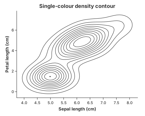
//! Single-colour density contour, with `mark_contour`.
//!
//! The same iso-lines as `density_contour.rs`, but with the marks'
//! colour-by-level turned off, so every line uses the outline colour instead.

use charton::prelude::*;
use std::error::Error;

fn main() -> Result<(), Box<dyn Error>> {
    let iris = load_dataset("iris")?;

    chart!(&iris)?
        .transform_density_2d(
            // Pad the estimation grid so the outer iso-lines close before its
            // edge instead of being clipped by it.
            Density2DTransform::new("sepal_length", "petal_length")
                .with_grid_size(60)
                .with_padding(0.3),
        )?
        .mark_contour("density")?
        .configure_contour(|contour| {
            contour
                .with_levels(10)
                .with_color_by_level(false)
                .with_stroke("black")
                .with_stroke_width(1.0)
        })
        .encode((alt::x("x"), alt::y("y")))?
        .with_title("Single-colour density contour")
        .with_x_label("Sepal length (cm)")
        .with_y_label("Petal length (cm)")
        .save("docs/src/images/contour_single.svg")?;

    println!("Saved docs/src/images/contour_single.svg");
    Ok(())
}
From scattered points
A bivariate density is just another scalar grid, so transform_density_2d feeds
mark_contour("density") — the familiar kdeplot / geom_density_2d picture.
The grid can also be drawn filled instead of as lines. Both are on the
2-D Density page:
scatter → transform_density_2d → mark_contour
Built from the primitives
The same picture without mark_contour: transform_contour turns the grid into
polylines and mark_path draws them, coloured by level.
//! Contour plot — built by hand from the primitives.
//!
//! The same picture as `contour.rs`, without `mark_contour`. A contour is a
//! **composition**, not a dedicated chart type:
//!
//! ```text
//! contour = iso-line stat (marching squares)  +  open-path geometry
//! ```
//!
//! * `transform_contour` (marching squares) turns a gridded `z` into
//!   `(x, y, path_group, level)` polylines;
//! * `mark_path` draws those polylines, coloured by `level`.
//!
//! The scalar grid is *your* data, so `transform_contour` reads `x`, `y`, `z`
//! and replaces the table with `x`, `y`, `path_group`, `level`. In `encode` you
//! then map those columns to channels: `x`/`y` to the axes, `path_group` groups
//! the vertices into separate lines, and `level` colours each line.

use charton::prelude::*;
use std::error::Error;

fn main() -> Result<(), Box<dyn Error>> {
    // Sample z = sin(x) * cos(y) on a regular grid.
    let n = 41;
    let mut x = Vec::new();
    let mut y = Vec::new();
    let mut z = Vec::new();
    for i in 0..n {
        for j in 0..n {
            let xv = -3.0 + 6.0 * i as f64 / (n as f64 - 1.0);
            let yv = -3.0 + 6.0 * j as f64 / (n as f64 - 1.0);
            x.push(xv);
            y.push(yv);
            z.push((xv).sin() * (yv).cos());
        }
    }

    chart!(x, y, z)?
        .transform_contour(ContourTransform::new("x", "y", "z").with_levels(10))?
        .mark_path()?
        .configure_path(|m| m.with_stroke_width(1.5))
        .encode((
            alt::x("x"),
            alt::y("y"),
            alt::path_group("path_group"),
            alt::color("level"),
        ))?
        .configure_theme(|t| t.with_color_map(ColorMap::Viridis))
        .with_title("Contour plot")
        .with_x_label("x")
        .with_y_label("y")
        .save("target/example-output/contour_manual.svg")?;

    println!("Saved target/example-output/contour_manual.svg");
    Ok(())
}
See also
- 2-D Density — density contours and density heatmaps.
- Heatmaps —
mark_rectover binned data. - The Layer Pipeline — the stat/position/geom model behind all of this.
- Composing Your Own — recombining the primitives into new pictures the marks do not cover.
examples/contour.rs,examples/contour_manual.rs,examples/contour_single.rs,examples/density_contour.rs.
Pie, Donut, Rose & Nightingale
All four are the same primitive: a bar on a polar coordinate system. Change the coordinate, the stacking and the angle, and the bar becomes a wedge, a ring, a petal or a polar-area chart. No pie-specific mark exists or is needed.
Pie
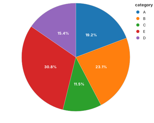
use charton::prelude::*;
use std::error::Error;

fn main() -> Result<(), Box<dyn Error>> {
    // Create sample data frame for donut chart
    let category = ["A", "B", "C", "E", "D", "E"];
    let value = [25.0, 30.0, 15.0, 30.0, 20.0, 10.0];

    // Create donut chart
    chart!(category, value)?
        .mark_bar()?
        .encode((
            alt::x(""),             // x encoding for donut chart (empty string for donut chart)
            alt::y("value"),        // theta encoding for donut slices
            alt::color("category"), // color encoding for different segments
        ))?
        .with_coord(CoordSystem::Polar)
        .save("docs/src/images/pie.svg")?;

    Ok(())
}
Donut
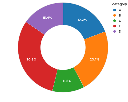
The same wedges with a hole: an inner radius on the polar coordinate.
use charton::prelude::*;
use std::error::Error;

fn main() -> Result<(), Box<dyn Error>> {
    // Create sample data frame for donut chart
    let category = ["A", "B", "C", "E", "D", "E"];
    let value = [25.0, 30.0, 15.0, 30.0, 20.0, 10.0];

    // Create donut chart
    let donut = chart!(category, value)?
        .mark_bar()?
        .encode((
            alt::x(""),             // x encoding for donut chart (empty string for donut chart)
            alt::y("value"),        // theta encoding for donut slices
            alt::color("category"), // color encoding for different segments
        ))?
        .with_coord(CoordSystem::Polar)
        .with_inner_radius(0.5);

    donut.save("docs/src/images/donut.svg")?;

    Ok(())
}
Rose (polar bar)
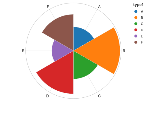
Bars whose height is a radius, arranged by angle.
use charton::prelude::*;
use std::error::Error;

fn main() -> Result<(), Box<dyn Error>> {
    // 1. Create a DataFrame with high-variance values to emphasize radial differences.
    // We use 6 categories ("A" through "F") to fill the polar coordinate space evenly.
    let type1 = ["A", "B", "C", "D", "E", "F"];
    // Data values range from 2.0 to 12.0 to create a clear "petal" effect
    let value = [3.0, 11.5, 4.2, 9.8, 2.5, 7.0];

    // 2. Build the bar chart
    // In a Polar Coordinate system, x-axis maps to the Angle (theta)
    // and y-axis maps to the Radius (r).
    chart!(type1, value)?
        .mark_bar()?
        .encode((
            alt::x("type1"),     // Each category represents a slice of the circle
            alt::y("value"),     // The height of the bar becomes the radius of the slice
            alt::color("type1"), // Distinct colors for each "petal"
        ))?
        .with_y_label("Intensity")
        // CoordSystem::Polar transforms the rectangular bar chart into a Rose Chart
        .with_coord(CoordSystem::Polar)
        .with_grid(true)
        .save("docs/src/images/rose.svg")?;

    Ok(())
}
Nightingale (polar area)
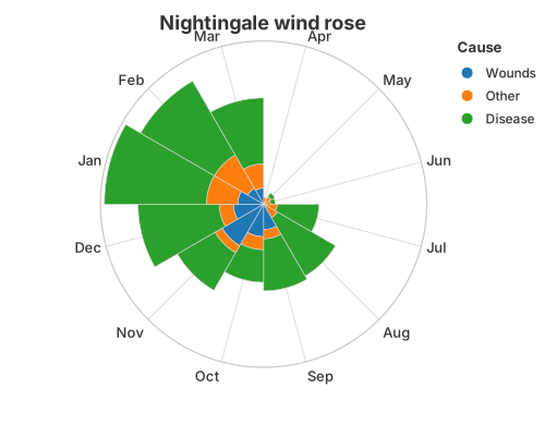
Equal angles, radius proportional to the value — Florence Nightingale's coxcomb.
use charton::prelude::*;
use std::error::Error;

fn main() -> Result<(), Box<dyn Error>> {
    let ds = load_dataset("nightingale")?;
    println!("{:?}", ds);

    chart!(ds)?
        .mark_bar()?
        .encode((
            alt::x("Month"),
            alt::y("Deaths").with_stack("stacked").with_normalize(false),
            alt::color("Cause"),
        ))?
        .with_title("Nightingale wind rose")
        .with_coord(CoordSystem::Polar)
        .with_grid(true)
        .save("docs/src/images/nightingale.svg")?;

    Ok(())
}
See also
- Coordinate Systems — how
CoordSystem::Polarturns Cartesian positions into angles and radii.
Faceting
Faceting draws the same layers once per panel. It is a property of the chart, not of any mark, so every recipe on this site can be faceted by adding one call.
Grid faceting (two dimensions)
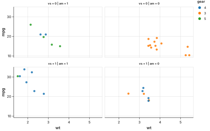
Arrange panels by two categorical columns — here vs across and am down.
//! Grid faceting: arrange panels by two categorical dimensions.
//!
//! The built-in `mtcars` dataset contains observations for all four `vs x am`
//! combinations. Each panel therefore has real vehicle observations instead
//! of empty combinations produced by sparse categorical fields.

use charton::prelude::*;
use std::error::Error;

fn main() -> Result<(), Box<dyn Error>> {
    let ds = load_dataset("mtcars")?;

    Chart::build(ds)?
        .mark_point()?
        .configure_point(|point| point.with_size(4.0).with_opacity(0.85))
        .encode((
            alt::x("wt"),
            alt::y("mpg"),
            alt::color("gear").with_scale(Scale::Discrete),
        ))?
        // vs: engine shape (0 = V-shaped, 1 = straight)
        // am: transmission (0 = automatic, 1 = manual)
        .facet(FacetSpec::grid("vs", "am").with_strategy("fixed"))
        .with_size(800, 500)
        .with_left_margin(0.0)
        .with_top_margin(0.0)
        .with_bottom_margin(0.0)
        .save("docs/src/images/facet_grid.svg")?;

    println!("Saved docs/src/images/facet_grid.svg");
    Ok(())
}
Wrap faceting (one dimension)
A single categorical column wrapped into a grid. See the
faceted violin for a complete example,
or tests/test_facet_wrap.rs for the unemployment-by-country recipe.
Free scales
By default every panel shares one scale (the point of faceting: panels are
comparable). FacetSpec::wrap(...).with_strategy("free") (and free_x /
free_y) lets each panel train its own, for panels whose ranges differ wildly.
See also
Geospatial
Map polygons are mark_geoshape with a path_group per region; points and
labels layer on top with the ordinary marks. The projection is a property of the
coordinate system.
World map
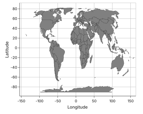
use charton::prelude::*;
use std::error::Error;

fn main() -> Result<(), Box<dyn Error>> {
    // World map geojson was downloaed from "https://raw.githubusercontent.com/nvkelso/natural-earth-vector/master/geojson/ne_110m_admin_0_countries.geojson";
    let world_map = std::path::Path::new("assets/ne_110m_admin_0_countries.geojson");

    let geojson_str = std::fs::read_to_string(world_map)?;

    let ds = geojson_to_dataset(&geojson_str)?;

    println!("Data loaded successfully!");
    println!("Total vertices: {}", ds.height());
    println!("Total columns: {}", ds.width());

    // Preview the first 10 vertices
    println!("\nFirst 10 vertices:");
    let preview = ds.select(&["NAME", "_lon", "_lat", "POP_EST", "_path_id"])?;
    println!("{:#?}", preview);

    // ==================== Draw the world map ====================
    println!("\nDrawing the world map...");

    let geo_layer = Chart::build(ds)?.mark_geoshape()?.encode((
        alt::x("_lon"),
        alt::y("_lat"),
        alt::path_group("_path_id"),
        //alt::color("POP_EST")
    ))?;

    geo_layer
        .with_x_label("Longitude")
        .with_y_label("Latitude")
        .with_coord(CoordSystem::Geo)
        .with_grid(true)
        .with_x_domain(-140.0, 150.0)
        //.with_size(1000, 500)
        .save("docs/src/images/world_map.svg")?;

    Ok(())
}
See also
- Coordinate Systems —
CoordSystem::Geoand the available projections.
Composing Your Own
The convenience marks cover the charts people ask for by name. This page is for everything else: how to assemble the public transforms and the Tier-1 geometries into a picture that no mark provides.
Read Design Rules: Marks, Tiers & Statistical Atoms for the tiers and the thin-recipe rule, and Transforms & Columns for the column each transform emits.
The pattern
A hand-written recipe is always three steps:
- stat — a
transform_*replaces the table with derived columns; - geom — a Tier-1 mark draws those columns;
- encode — map the emitted columns to channels (
x,y,path_group,color).
Every convenience mark is exactly this, and its expansion is written out on its own page under "Built from the primitives":
| Mark | Hand-written version |
|---|---|
mark_density | 1-D Density → Built from the primitives |
mark_violin | Violin → Built from the primitives |
mark_density (cumulative) | Cumulative Density → Built from the primitives |
mark_contour | Contour Plots → Built from the primitives |
A new composition: the mirrored density
Recombining means choosing a different geom for the same stat — or the other
way round. mark_violin pairs transform_density with transform_band (a
mirrored polygon). Pair the same density with mark_area and
stack: "center" instead and you get a mirrored density: each curve is drawn
from -density / 2 to +density / 2. This is the Vega-Lite
density + area + stack recipe, and it is the right choice when you want the
untrimmed tail rather than the data-bounded violin.
//! Mirrored density — a new picture recombined from the primitives.
//!
//! `mark_violin` pairs `transform_density` with `transform_band` (a mirrored
//! polygon). This example pairs the *same* statistic with `mark_area` and
//! `stack: "center"` instead: each curve is drawn from `-density / 2` to
//! `+density / 2`, then `coord_flip` stands it upright. It is the Vega-Lite
//! `density + area + stack` recipe, and it keeps the untrimmed tail rather than
//! stopping at the data like a violin.

use charton::prelude::*;
use std::error::Error;

fn main() -> Result<(), Box<dyn Error>> {
    let iris = load_dataset("iris")?;

    chart!(iris)?
        .transform_density(
            DensityTransform::new("sepal_length")
                .with_as("sepal_length", "density")
                .with_groupbys(["species"]),
        )?
        .mark_area()?
        .configure_area(|area| area.with_opacity(0.6).with_stroke("#2c3e50"))
        .encode((
            alt::x("sepal_length"),
            alt::y("density").with_stack("center"),
            alt::color("species"),
        ))?
        .coord_flip()
        .with_title("Mirrored density")
        .with_x_label("Density")
        .with_y_label("Sepal length (cm)")
        .save("target/example-output/density_mirror.svg")?;

    println!("Saved target/example-output/density_mirror.svg");
    Ok(())
}
A ridgeline from a half-band
A ridgeline stacks one density per category, each sitting on its baseline and
overlapping the one above. mark_violin uses a symmetric band;
transform_band(…).with_side(BandSide::Right) keeps only one bank, so the flat
edge of the polygon is the baseline. with_overlap(2.5) grows each ridge past
its lane so the densities overlap, and coord_flip puts the value on the
horizontal axis and the density bulge on the vertical one.
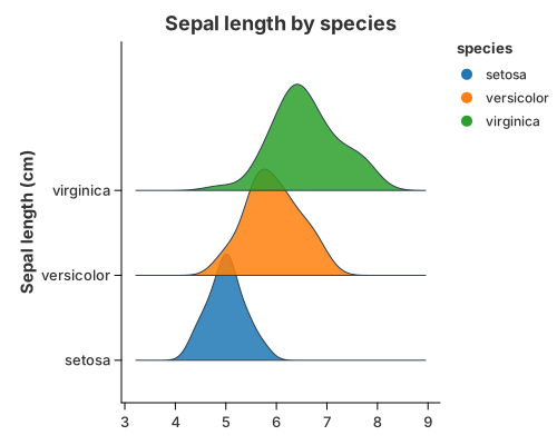
//! Ridgeline — one density per category, each sitting on its baseline.
//!
//! This is a composition, not a mark. The density comes from
//! `transform_density`; `transform_band(…).with_side(BandSide::Right)` turns each
//! curve into a one-sided band whose flat edge is the category baseline; and
//! `coord_flip` puts the value on the horizontal axis and the density bulge on
//! the vertical one. `with_overlap` lets each ridge grow past its lane so it
//! overlaps the one above it. A ridge is a violin that keeps one bank.
//!
//! The category axis is trained from the numeric positions the band emits, so
//! the tallest ridge is never clipped even though it grows past the last
//! category. The recipe needs no hand-written expansion.

use charton::prelude::*;
use std::error::Error;

fn main() -> Result<(), Box<dyn Error>> {
    let iris = load_dataset("iris")?;

    chart!(iris)?
        .transform_density(
            DensityTransform::new("sepal_length")
                .with_as("sepal_length", "density")
                .with_groupbys(["species"]),
        )?
        .transform_band(
            BandTransform::new("sepal_length", "density")
                .with_center("species")
                .with_side(BandSide::Right)
                .with_width(1.0)
                .with_overlap(2.5)
                .with_scale(BandScale::PerGroup),
        )?
        .mark_polygon()?
        .configure_geoshape(|mark| {
            mark.with_opacity(0.85)
                .with_stroke("#2c3e50")
                .with_stroke_width(1.0)
        })
        .encode((
            // The category axis covers the band's real extent automatically:
            // a ridge grows past its lane, and the scale expands to include it.
            alt::x("x").with_category_labels("species"),
            alt::y("y"),
            alt::path_group("path_group"),
            alt::color("species"),
        ))?
        .coord_flip()
        .with_title("Sepal length by species")
        .with_x_label("Sepal length (cm)")
        .with_y_label("")
        .save("docs/src/images/ridge.svg")?;

    println!("Saved docs/src/images/ridge.svg");
    Ok(())
}
The pieces are all public: transform_density estimates one curve per category,
transform_band mirrors it into a polygon and mark_polygon fills it. None of
this is ridge-specific: with_side(BandSide::Both) is the full violin, a
one-sided band is a half violin, and with_overlap is also how violins overlap.
See
The firewall
for why a ridgeline is a recipe rather than a mark.
One practical note: because a ridge grows past its lane, the category axis is
trained from the numeric positions the band actually emits. The axis expands
to include them, so the example needs no hand-written with_expansion; use it
only when you want more (or less) breathing room than the automatic fit.
Choosing the geometry
For anything that "connects the dots", the geometry differs by exactly two flags: open or closed and sorted by x or in row order.
| Geometry | Order | Grouped by | Closed? | Filled? |
|---|---|---|---|---|
mark_line | sorted by x | color | no | no |
mark_path | row order | path_group | no | no |
mark_polygon / mark_geoshape | row order | path_group | yes | yes |
So a contour (mark_path, open) and a violin (mark_polygon, closed) are the
same geometry one flag apart. See
Connecting the dots.
When to stop composing
If you keep rebuilding the same picture, that is the signal to add a mark — but
only if it passes the
promotion checklist. A split violin is a
parameter of mark_violin; a raincloud is a stack of layers, so it stays a
recipe. The rule of thumb: a name that is a geometry/statistic atom (violin,
contour) can become a mark; a name that is a metaphor for a whole picture
(raincloud, waterfall) is a composition.
See also
- Transforms & Columns — the full column contract.
- Marks & Geometries — the Tier-1 vocabulary
(
mark_point,mark_path,mark_polygon, …). - Design Rules — tiers, the thin-recipe rule, and when a new mark is justified.
Semaglutide Weight Loss Curve (NEJM 2021)
Background
This figure is a reproduction of Figure 1A from the landmark study "Once-Weekly Semaglutide in Adults with Overweight or Obesity", published in The New England Journal of Medicine (NEJM) in 2021. The study evaluates the efficacy and safety of semaglutide as a pharmacological intervention for weight management.
The plot illustrates the mean percentage change in body weight over a 68-week period. It highlights the significant divergence in weight loss trajectories between the semaglutide group and the placebo group, both of which were conducted alongside lifestyle interventions.
Data Acquisition
The data used for this visualization was extracted from the original publication using WebPlotDigitizer.
Implementation
Using Charton’s "Grammar of Graphics" approach, we can recreate this complex clinical plot by layering multiple graphical components, enabling highly flexible and customizable visualizations with concise Rust code.
use charton::prelude::*;
use std::error::Error;

// The data is obtained from paper "Once-Weekly Semaglutide in Adults with Overweight or Obesity"
// using [webplotdigitizer](https://automeris.io/).
fn main() -> Result<(), Box<dyn Error>> {
    // Placebo group data (control group)
    let ds_placebo = vec![
        // X-axis: time since randomization (weeks)
        (
            "Weeks since Randomization",
            [0, 4, 8, 12, 16, 20, 28, 36, 44, 52, 60, 68].into_column(),
        ),
        // Y-axis: mean percentage change in body weight from baseline. Negative values indicate weight loss
        (
            "Change from Baseline (%)",
            [
                0.00, -1.11, -1.72, -2.18, -2.54, -2.83, -2.82, -2.98, -3.24, -3.31, -3.22, -2.76,
            ]
            .into_column(),
        ),
        // Lower bound of the confidence interval (typically 95% CI)
        (
            "lower",
            [
                -0.042, -1.18, -1.81, -2.28, -2.66, -3.00, -3.03, -3.22, -3.49, -3.54, -3.46, -3.03,
            ]
            .into_column(),
        ),
        // Upper bound of the confidence interval (95% CI)
        (
            "upper",
            [
                0.042, -1.04, -1.63, -2.08, -2.42, -2.66, -2.61, -2.74, -2.99, -3.08, -2.98, -2.49,
            ]
            .into_column(),
        ),
    ]
    .to_dataset()?;

    // Semaglutide group data (treatment group)
    let ds_semaglutide = vec![
        (
            "Weeks since Randomization",
            [0, 4, 8, 12, 16, 20, 28, 36, 44, 52, 60, 68].into_column(),
        ),
        (
            "Change from Baseline (%)",
            [
                0.00, -2.27, -4.01, -5.9, -7.66, -9.46, -11.68, -13.33, -14.62, -15.47, -15.86,
                -15.6,
            ]
            .into_column(),
        ),
        (
            "lower",
            [
                -0.041, -2.3, -4.1, -5.98, -7.79, -9.58, -11.84, -13.55, -14.83, -15.72, -16.13,
                -15.86,
            ]
            .into_column(),
        ),
        (
            "upper",
            [
                0.041, -2.24, -3.92, -5.82, -7.53, -9.34, -11.52, -13.11, -14.41, -15.22, -15.59,
                -15.34,
            ]
            .into_column(),
        ),
    ]
    .to_dataset()?;

    // Text labels (placed at the right side of the plot)
    let ds_text = vec![
        ("x", [68.8, 68.8].into_column()),
        ("y", [-3.05, -15.86].into_column()),
        ("group", ["Placebo", "Semaglutide"].into_column()),
    ]
    .to_dataset()?;

    // Reference line (y = 0 → no weight change)
    let ds_reference = vec![
        ("x", [0.0, 76.0].into_column()),
        ("y", [0.0, 0.0].into_column()),
    ]
    .to_dataset()?;

    // Layer 1: Placebo points (markers at each time point)
    let placebo_point = Chart::build(&ds_placebo)?
        .mark_point()?
        .configure_point(|p| {
            p.with_color("#818284")
                .with_shape("triangle")
                .with_size(5.0)
        })
        .encode((
            alt::x("Weeks since Randomization"),
            alt::y("Change from Baseline (%)"),
        ))?;

    // Layer 2: Placebo line (connects the points)
    let placebo_line = Chart::build(&ds_placebo)?
        .mark_line()?
        .configure_line(|l| l.with_color("#818284"))
        .encode((
            alt::x("Weeks since Randomization"),
            alt::y("Change from Baseline (%)"),
        ))?;

    // Layer 3: Placebo error bars (confidence intervals)
    let placebo_errorbar = Chart::build(&ds_placebo)?
        .mark_errorbar()?
        .configure_errorbar(|e| {
            e.with_color("#818284")
                .with_cap_length(4.0)
                .with_stroke_width(1.5)
        })
        .encode((
            alt::x("Weeks since Randomization"),
            alt::y("lower"),
            alt::y2("upper"),
        ))?;

    // Layer 4: Placebo text label
    let placebo_text = Chart::build(ds_text.head(1))?
        .mark_text()?
        .configure_text(|t| t.with_anchor("left").with_size(14.0))
        .encode((alt::x("x"), alt::y("y"), alt::text("group")))?;

    // Layer 5: Semaglutide points
    let semaglutide_point = Chart::build(&ds_semaglutide)?
        .mark_point()?
        .configure_point(|p| p.with_color("#5b88c3").with_shape("square").with_size(3.0))
        .encode((
            alt::x("Weeks since Randomization"),
            alt::y("Change from Baseline (%)"),
        ))?;

    // Layer 6: Semaglutide line
    let semaglutide_line = Chart::build(&ds_semaglutide)?
        .mark_line()?
        .configure_line(|l| l.with_color("#5b88c3"))
        .encode((
            alt::x("Weeks since Randomization"),
            alt::y("Change from Baseline (%)"),
        ))?;

    // Layer 7: Semaglutide error bars
    let semaglutide_errorbar = Chart::build(&ds_semaglutide)?
        .mark_errorbar()?
        .configure_errorbar(|e| {
            e.with_color("#5b88c3")
                .with_cap_length(4.0)
                .with_stroke_width(1.5)
        })
        .encode((
            alt::x("Weeks since Randomization"),
            alt::y("lower"),
            alt::y2("upper"),
        ))?;

    // Layer 8: Semaglutide text label
    let semaglutide_text = Chart::build(ds_text.tail(1))?
        .mark_text()?
        .configure_text(|t| t.with_anchor("left").with_size(14.0))
        .encode((alt::x("x"), alt::y("y"), alt::text("group")))?;

    // Layer 9: Reference line (baseline at 0%)
    let reference_line = Chart::build(&ds_reference)?
        .mark_line()?
        .configure_line(|l| l.with_dash([6.0, 6.0]))
        .encode((alt::x("x"), alt::y("y")))?;

    // Combine all layers (Grammar of Graphics composition)
    placebo_point
        .and(reference_line)
        .and(placebo_line)
        .and(placebo_errorbar)
        .and(placebo_text)
        .and(semaglutide_point)
        .and(semaglutide_line)
        .and(semaglutide_errorbar)
        .and(semaglutide_text)
        .with_x_expand(Expansion {
            mult: (0.00, 0.0),
            add: (0.0, 0.0),
        })
        .with_y_expand(Expansion {
            mult: (0.15, 0.01),
            add: (0.0, 0.0),
        })
        .with_size(1000, 400)
        .with_right_margin(0.08)
        .with_left_margin(0.02)
        .with_top_margin(0.02)
        .with_bottom_margin(0.03)
        .with_x_ticks([
            0.0, 4.0, 8.0, 12.0, 16.0, 20.0, 28.0, 36.0, 44.0, 52.0, 60.0, 68.0,
        ])
        .with_y_ticks([
            0.0, -2.0, -4.0, -6.0, -8.0, -10.0, -12.0, -14.0, -16.0, -18.0,
        ])
        .save("docs/src/images/weight_loss_curve.svg")?;

    Ok(())
}

Feature Analysis for Classification (Iris)
Background
Before training a classifier you look at two things: how each feature is distributed within each class, and whether the classes are separable in feature space. This study uses the classic Iris dataset — three species, four measurements — to reproduce those two views with the convenience marks.
Class-conditional distributions
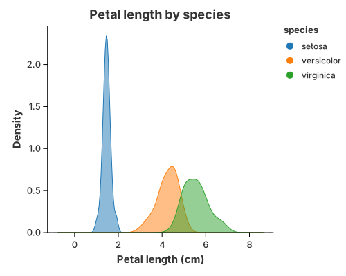
mark_density reads the feature from x and gives one curve per color group,
so you can see how a feature separates the classes. Petal length is clearly
bimodal: setosa sits far to the left, while versicolor and virginica
overlap in the middle. A single threshold on this feature would split setosa
perfectly but confuse the other two.
Feature separation
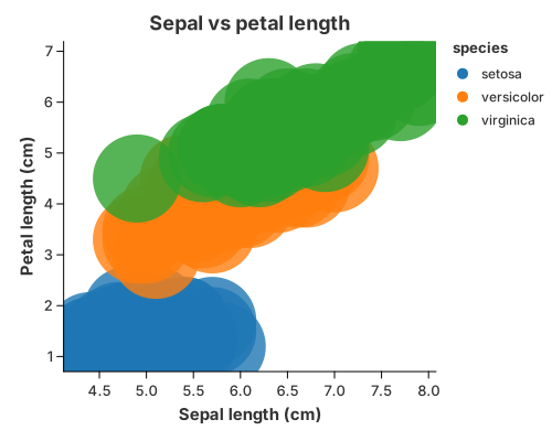
A scatter of two features, coloured by class, shows the decision boundary a linear model would try to find. Setosa is linearly separable from the other two; versicolor and virginica share a region where any straight boundary has to trade false positives for false negatives.
Implementation
//! Case study: exploratory feature analysis before training a classifier.
//!
//! Two views you would actually look at on the Iris dataset:
//!
//! 1. the **class-conditional distribution** of a feature (is it separable?),
//! 2. a **scatter of two features**, coloured by class, to see the decision
//!    boundary a linear model would find.

use charton::prelude::*;
use std::error::Error;

fn main() -> Result<(), Box<dyn Error>> {
    let iris = load_dataset("iris")?;

    // 1. Class-conditional density of petal length.
    chart!(&iris)?
        .mark_density()?
        .configure_density(|density| density.with_opacity(0.5))
        .encode((alt::x("petal_length"), alt::color("species")))?
        .with_title("Petal length by species")
        .with_x_label("Petal length (cm)")
        .with_y_label("Density")
        .save("docs/src/images/case_data_science_density.svg")?;

    // 2. Two features, coloured by class. Setosa is linearly separable from the
    //    other two; versicolor and virginica overlap.
    chart!(&iris)?
        .mark_point()?
        .configure_point(|point| point.with_size(40.0).with_opacity(0.8))
        .encode((
            alt::x("sepal_length"),
            alt::y("petal_length"),
            alt::color("species"),
        ))?
        .with_title("Sepal vs petal length")
        .with_x_label("Sepal length (cm)")
        .with_y_label("Petal length (cm)")
        .save("docs/src/images/case_data_science_scatter.svg")?;

    println!("Saved case_data_science_density.svg and case_data_science_scatter.svg");
    Ok(())
}
Both figures are a single encoding each: y/x for the values and color for
the class. The axis and legend titles come from the original columns
(petal_length, sepal_length, species) automatically.
What it demonstrates
mark_densityfor class-conditional distributions, one curve per group.mark_point+colorfor feature separation and decision boundaries.- The grammar behind both: a density is
transform_density+mark_area; a scatter ismark_point. See 1-D Density and Scatter.
See also
- Violin — the same distributions as an outline with an inner box.
- 2-D Density — the joint distribution of two features.
- Scatter matrices — the full pairwise view.
Risk Dashboard for an Equity Index
Background
A small risk view of a market series has two halves: the level over time and the distribution of returns. The first shows the path; the second shows the drift, the volatility and (if present) the tails that drive risk.
The series here is synthetic and deterministic — a small positive drift plus a periodic volatility component, generated without any random number generator — so the example is fully reproducible.
Index level over time
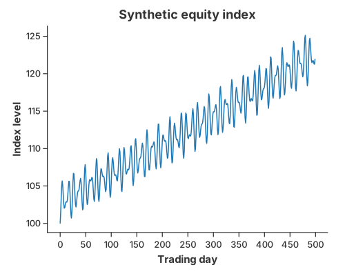
mark_line draws the index against the trading day. The up-drift is visible, but
so are the drawdowns and the changing volatility (the calm and turbulent
stretches come from the periodic term).
Distribution of daily returns
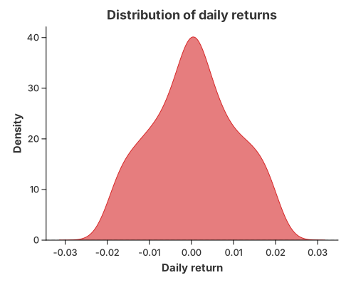
mark_density of the daily returns gives the risk picture: the curve is
off-centre (positive drift) and its width is the volatility. A real
return series would also show fat tails — more mass far from the centre than a
normal distribution predicts — which is what a risk model has to capture.
Implementation
//! Case study: a small "risk dashboard" for a synthetic equity index.
//!
//! Two figures:
//!
//! 1. the **index level** over time, and
//! 2. the **distribution of daily returns**, which is where tail risk shows up.
//!
//! The series is generated deterministically (no external RNG), so the example is
//! reproducible.

use charton::prelude::*;
use std::error::Error;

fn main() -> Result<(), Box<dyn Error>> {
    // Deterministic synthetic daily returns: a small positive drift plus a
    // periodic volatility component.
    let n = 500;
    let mut day = Vec::with_capacity(n);
    let mut price = Vec::with_capacity(n);
    let mut ret = Vec::with_capacity(n);

    let mut level = 100.0_f64;
    for i in 0..n {
        let t = i as f64;
        let r = 0.0004 + 0.02 * (t * 0.7).sin() * (t * 0.13).cos();
        level *= 1.0 + r;
        day.push(t);
        price.push(level);
        ret.push(r);
    }

    // 1. Index level over time.
    chart!(day, price)?
        .mark_line()?
        .configure_line(|line| line.with_color("#1f77b4").with_stroke_width(1.5))
        .encode((alt::x("day"), alt::y("price")))?
        .with_title("Synthetic equity index")
        .with_x_label("Trading day")
        .with_y_label("Index level")
        .save("docs/src/images/case_finance_series.svg")?;

    // 2. Distribution of daily returns.
    chart!(day, ret)?
        .mark_density()?
        .configure_density(|density| density.with_color("#d62728").with_opacity(0.6))
        .encode(alt::x("ret"))?
        .with_title("Distribution of daily returns")
        .with_x_label("Daily return")
        .with_y_label("Density")
        .save("docs/src/images/case_finance_returns.svg")?;

    println!("Saved case_finance_series.svg and case_finance_returns.svg");
    Ok(())
}
The data is built in plain Rust vectors and handed to chart!; the two figures
are then a mark_line and a mark_density, each with an explicit visual style
via configure_line / configure_density.
What it demonstrates
mark_linefor a time series, with the colour set explicitly.mark_densityfor a return distribution, one line to draw.- The grammar underneath: the density is
transform_density+mark_area(mark_density); the line is a singlemark_line.
See also
- 1-D Density — tuning the smoothing (bandwidth, kernel).
- Cumulative Density — the distribution as a CDF, useful for value-at-risk style questions.
- Line Charts — trends and multiple series.
Economist-Style Highlights: AI Investment
Background
A recurring request is to reproduce the visual language of The Economist: a small number of focus series drawn in strong colours and a heavier stroke, while every other series recedes into thin grey context. The original report (issue about legend and label customisation) also needed two things Charton did not offer at the time:
- the legend had to be renamed and positioned at the top;
- the y axis had to read
$20B, not2.0000E10or20000000000.
This case study rebuilds that chart with synthetic data, so it runs without any external file.
Strategy
The chart is assembled in three moves:
- Split the data into the areas that should stand out and the areas that provide context.
- Layer the two charts with
.and(). The context layer uses a thinner stroke, so the two layers genuinely differ. - Format the labels.
LabelFormathandles both the axis ($0…$60B) and the legend entries (long data names become short, readable ones).
Implementation
//! Economist-style chart: highlighted focus areas over greyed-out context.
//!
//! This mirrors the layering strategy from the issue: one chart for the series
//! that should stand out, one for the rest, combined with `.and()`. The data is
//! synthetic, so the example runs without any external file.
//!
//! The palette and the legend position describe the whole chart, so they are
//! applied once to the combined result instead of to either layer.
//!
//! Run with: `cargo run --example economist_chart`

use charton::prelude::*;

/// Focus areas that get their own colour and a legend entry.
const HIGHLIGHTED: [(&str, f64, f64); 5] = [
    ("Data management, processing, cloud", 4.0e9, 1.45),
    ("Medical and healthcare", 3.0e9, 1.55),
    ("Retail", 1.5e9, 1.35),
    ("Natural language, customer support", 2.0e9, 1.50),
    ("Facial recognition", 1.0e9, 1.40),
];

/// Every other focus area, drawn as grey context.
const CONTEXT: [(&str, f64, f64); 4] = [
    ("Autonomous vehicles", 2.5e9, 1.30),
    ("Computer vision", 1.2e9, 1.25),
    ("Generative AI", 0.5e9, 1.60),
    ("Other", 0.8e9, 1.20),
];

/// Deterministic synthetic series: `base * growth^year`, 2015..=2022.
fn build(entities: &[(&str, f64, f64)]) -> Result<Dataset, Box<dyn std::error::Error>> {
    let mut year = Vec::new();
    let mut entity = Vec::new();
    let mut investment = Vec::new();

    for (name, base, growth) in entities {
        for offset in 0..8 {
            year.push((2015 + offset).to_string());
            entity.push((*name).to_string());
            investment.push(base * growth.powi(offset));
        }
    }

    Ok(Dataset::new()
        .with_column("Year", year)?
        .with_column("Entity", entity)?
        .with_column("investment", investment)?)
}

fn main() -> Result<(), Box<dyn std::error::Error>> {
    let highlight_ds = build(&HIGHLIGHTED)?;
    let context_ds = build(&CONTEXT)?;

    // The palette is indexed by the colour domain, and the merged domain lists
    // the first layer's categories first. So it is built as "one colour per
    // focus area, then grey for every context area".
    let mut palette: Vec<SingleColor> = ["#17648d", "#51bec7", "#008c8f", "#d6ab63", "#843844"]
        .iter()
        .map(|hex| (*hex).into())
        .collect();
    palette.extend(std::iter::repeat_n(
        SingleColor::from("#d4dddd"),
        CONTEXT.len(),
    ));

    // 20_000_000_000 -> "$20B".
    let money = LabelFormat::new()
        .with_prefix("$")
        .with_compact_notation()
        .with_precision(0);

    let short_names = LabelFormat::new().with_text_formatter(|label| {
        match label {
            "Data management, processing, cloud" => "Data & cloud",
            "Medical and healthcare" => "Healthcare",
            "Natural language, customer support" => "NLP & support",
            other => other,
        }
        .to_string()
    });

    let highlight_chart = Chart::build(highlight_ds)?
        .mark_line()?
        .configure_line(|line| line.with_stroke_width(1.25))
        .encode((alt::x("Year"), alt::y("investment"), alt::color("Entity")))?
        .with_title("Annual global private investment in artificial intelligence, by focus area")
        .with_y_label("")
        .with_color_label("Focus area")
        .with_y_label_format(money)
        .with_legend_label_format(short_names);

    let base_chart = Chart::build(context_ds)?
        .mark_line()?
        .configure_line(|line| line.with_stroke_width(0.75))
        .encode((alt::x("Year"), alt::y("investment"), alt::color("Entity")))?;

    highlight_chart
        .and(base_chart)
        .with_size(760, 480)
        // Palette and legend position describe the whole chart, not a single
        // layer, so they are set once after the layers have been combined.
        .configure_theme(|theme| {
            theme
                .with_palette(ColorPalette::Custom(palette))
                .with_legend_position(LegendPosition::Top)
        })
        .save("docs/src/images/economist_chart.svg")?;

    Ok(())
}
What to notice
Formatting is attached to the chart, not the theme
#![allow(unused)]
fn main() {
let money = LabelFormat::new()
    .with_prefix("$")
    .with_compact_notation()   // 20_000_000_000 -> 20B
    .with_precision(0);
}
with_y_label_format applies it to the axis, with_legend_label_format to the
legend entries and the colour bar. A closure can replace either one entirely:
#![allow(unused)]
fn main() {
LabelFormat::new().with_text_formatter(|label| match label {
    "Medical and healthcare" => "Healthcare",
    other => other,
})
}
The same formatter is used when the layout engine measures the labels, so the axis reserves exactly the width the formatted text occupies.
Renaming a legend is not renaming a field
with_color_label("Focus area") changes only the legend title. The data column
stays Entity, so colours and grouping are unaffected. This is why the title
lives on the aesthetic mapping separately from the field name.
Theme settings belong to the whole chart
with_palette and with_legend_position describe the figure as a whole, so
they are applied once, after .and() has combined the layers:
#![allow(unused)]
fn main() {
highlight_chart
    .and(base_chart)
    .with_size(760, 480)
    .configure_theme(|theme| {
        theme
            .with_palette(ColorPalette::Custom(palette))
            .with_legend_position(LegendPosition::Top)
    })
}
Setting them on a single layer would be misleading: when two charts are combined, only the left one's theme survives, so a setting written on the right layer is silently dropped. The merged colour domain still lists the first layer's categories first, so the palette is built as one colour per focus area, then grey for every context area:
#![allow(unused)]
fn main() {
let mut palette: Vec<SingleColor> = ["#17648d", "#51bec7", "#008c8f", "#d6ab63", "#843844"]
    .iter()
    .map(|hex| (*hex).into())
    .collect();
palette.extend(std::iter::repeat_n(SingleColor::from("#d4dddd"), CONTEXT.len()));
}
The context layer only sets its thinner stroke width; the palette and the legend are supplied by the combined chart and cover every category.
Using the real dataset
The synthetic series above follow the same shape as the original CSV. With Polars, the split is a one-line mask instead of two constants:
#![allow(unused)]
fn main() {
let ds = load_polars_df!(df.filter(&mask)?)?;              // focus areas
let ds_context = load_polars_df!(df.filter(&!mask)?)?;     // everything else
}
Both datasets keep the same column names, so the chart code is unchanged.
The 50k-Point Lorenz Attractor (WGPU & Zero-Allocation WASM)
The previous chapter's WGPU implementation (Chapter WebAssembly, Part 2) was a "naive" port that re-allocated heap memory every frame. To push WebAssembly and your GPU to their limits, we will render a Lorenz Attractor—a complex, non-repeating 3D trajectory—simulating 50,000 dynamic particles at a locked 60 FPS.
Crucially, we will refactor our WASM boundary to achieve Zero-Allocation (Zero Malloc) during the render loop.
The Bottleneck: Why "Naive" WASM Stutters
Pushing Part 2's code to 50,000 points causes micro-stutters. The CPU, not the GPU, struggles with memory allocation. Our previous render_chart_gpu function ran this every frame:
#![allow(unused)]
fn main() {
let ds = Dataset::new()
    .with_column("x", xs.to_vec()) // Heap Allocation!
    // ...
}
Calling to_vec() 60 times a second on 50k points forces constant memory allocation and deallocation, choking the CPU and starving the GPU. The fix is shifting from a Stateless API to a Stateful Architecture using a persistent Rust struct to reuse memory.
Rust: The Stateful LiveChartApp
We will create a persistent Rust object that pre-allocates memory for our points at startup. During the animation loop, Charton's update_column_f64 performs an in-place memory copy, bypassing heap allocations entirely.
Update your Cargo.toml:
[package]
name = "lorenz"
version = "0.2.0"
edition = "2024"

[lib]
crate-type = ["cdylib"]

[dependencies]
wasm-bindgen = "0.2"
wasm-bindgen-futures = "0.4" # Required for awaiting asynchronous GPU adapters
charton = {version = "0.8", features = ["wgpu"] } # Enable WGPU feature

getrandom = { version = "0.3", features = ["wasm_js"] }

[profile.release]
opt-level = "s"
lto = true
codegen-units = 1
panic = "abort"
Update your src/lib.rs:
#![allow(unused)]
fn main() {
use charton::prelude::*;
use wasm_bindgen::prelude::*;

#[wasm_bindgen]
pub struct LiveChartApp {
    dataset: Dataset,
    canvas_id: String,
}

#[wasm_bindgen]
impl LiveChartApp {
    #[wasm_bindgen(constructor)]
    pub fn new(canvas_id: String, capacity: usize) -> Result<LiveChartApp, JsValue> {
        let zeros = vec![0.0; capacity];

        let dataset = Dataset::new()
            .with_column("x", zeros.clone())
            .map_err(|e| e.to_string())?
            .with_column("y", zeros.clone())
            .map_err(|e| e.to_string())?
            .with_column("intensity", zeros)
            .map_err(|e| e.to_string())?;

        Ok(Self { dataset, canvas_id })
    }

    pub async fn update_and_render(
        &mut self,
        xs: &[f64],
        ys: &[f64],
        colors: &[f64],
    ) -> Result<(), JsValue> {
        // Zero-allocation memory overwrite
        self.dataset
            .update_column_f64("x", xs)
            .map_err(|e| e.to_string())?;
        self.dataset
            .update_column_f64("y", ys)
            .map_err(|e| e.to_string())?;
        self.dataset
            .update_column_f64("intensity", colors)
            .map_err(|e| e.to_string())?;

        // Build lightweight declarative chart and flush to WGPU Canvas
        Chart::build(self.dataset.clone())
            .map_err(|e| e.to_string())?
            .mark_point()
            .map_err(|e| e.to_string())?
            .configure_point(|p| p.with_size(1.0).with_opacity(0.4))
            .encode((
                // Lock domain to avoid full scan, adaptively fit based on standard Lorenz range
                alt::x("x"),
                alt::y("y"),
                alt::color("intensity"),
            ))
            .map_err(|e| e.to_string())?
            // Responsive dimensions fully controlled by frontend canvas styles
            .configure_theme(|t| {
                t.with_background_color("#090d16")
                    .with_color_map(ColorMap::Plasma)
                    .with_show_axes(false)
                    .with_show_legend(false)
                    .with_top_margin(0.10)
                    .with_bottom_margin(0.0)
                    .with_left_margin(0.0)
                    .with_right_margin(0.0)
            })
            .render_to_canvas(&self.canvas_id)
            .await
            .map_err(|e| e.to_string())?;

        Ok(())
    }
}
}
JavaScript: Chaos Math & 3D Projection
In index.html, we calculate the Lorenz equations. To create a rotating 3D effect, we compute coordinates once, then apply a dynamic 3D-to-2D rotation matrix each frame before streaming data to WASM.
Replace index.html with this:
<!DOCTYPE html>
<html lang="en">
<head>
    <meta charset="UTF-8">
    <meta name="viewport" content="width=device-width, initial-scale=1.0">
    <title>Charton WASM — 50k Lorenz Chaos Engine</title>
    <style>
        :root {
            --bg-color: #05070f;
            --panel-bg: rgba(13, 17, 23, 0.75);
            --accent-color: #00f2ff;
            --accent-glow: rgba(0, 242, 255, 0.4);
            --text-color: #c9d1d9;
            --border-color: #21262d;
        }

        body {
            font-family: 'Segoe UI', system-ui, -apple-system, sans-serif;
            background: var(--bg-color);
            color: var(--text-color);
            margin: 0;
            padding: 0;
            height: 100vh;
            display: flex;
            justify-content: center;
            align-items: center;
            background: radial-gradient(circle at center, #0f1626 0%, #05070f 100%);
            overflow: hidden;
        }

        /* Main container: max width limited to 1080px */
        #app-container {
            display: flex;
            width: 90vw;
            max-width: 1080px;
            height: 80vh;
            max-height: 720px;
            background: #090d16;
            border-radius: 16px;
            border: 1px solid rgba(0, 242, 255, 0.15);
            box-shadow: 0 24px 60px rgba(0, 0, 0, 0.8);
            overflow: hidden;
        }

        /* Left panel: ultra-compact layout */
        #control-panel {
            width: 260px;
            background: var(--panel-bg);
            border-right: 1px solid var(--border-color);
            padding: 1.2rem;
            display: flex;
            flex-direction: column;
            gap: 0.8rem;
            box-sizing: border-box;
            backdrop-filter: blur(12px);
            height: 100%;
            overflow: hidden; /* Lock viewport, prevent scrollbars */
        }

        h2 {
            font-size: 0.95rem;
            margin: 0;
            color: #fff;
            text-transform: uppercase;
            letter-spacing: 1px;
            border-bottom: 2px solid var(--border-color);
            padding-bottom: 0.4rem;
            flex-shrink: 0;
        }

        .stats-box {
            background: rgba(255, 255, 255, 0.03);
            border: 1px solid var(--border-color);
            border-radius: 6px;
            padding: 0.4rem 0.6rem;
            font-family: monospace;
            font-size: 0.75rem;
            flex-shrink: 0;
        }

        .stat-line {
            display: flex;
            justify-content: space-between;
            margin-bottom: 0.15rem;
        }

        .stat-value {
            color: var(--accent-color);
            font-weight: bold;
            text-shadow: 0 0 8px var(--accent-glow);
        }

        #controls-container {
            flex: 1;
            display: flex;
            flex-direction: column;
            gap: 0.8rem;
            overflow: hidden;
        }

        .control-group {
            display: flex;
            flex-direction: column;
            gap: 0.2rem;
            flex-shrink: 0;
            box-sizing: border-box;
        }

        label {
            font-size: 0.75rem;
            color: #8b949e;
            display: flex;
            justify-content: space-between;
        }

        .label-val {
            color: #fff;
            font-family: monospace;
        }

        /* Ultra-thin slider style design */
        input[type="range"] {
            -webkit-appearance: none;
            -moz-appearance: none;
            appearance: none;

            width: 100%;
            background: #161b22;
            height: 4px;
            border-radius: 2px;
            outline: none;
            margin: 4px 0;
            flex-shrink: 0;
        }

        input[type="range"]::-webkit-slider-thumb {
            -webkit-appearance: none;
            appearance: none;

            width: 12px;
            height: 12px;
            border-radius: 50%;
            background: var(--accent-color);
            cursor: pointer;
            box-shadow: 0 0 6px var(--accent-color);
            transition: transform 0.1s;
        }

        input[type="range"]::-moz-range-thumb {
            border: none;
            width: 12px;
            height: 12px;
            border-radius: 50%;
            background: var(--accent-color);
            cursor: pointer;
            box-shadow: 0 0 6px var(--accent-color);
            transition: transform 0.1s;
        }

        /* Right canvas area */
        #stage {
            flex: 1;
            height: 100%;
            position: relative;
            background: #090d16;
        }

        #chart-canvas {
            width: 100%;
            height: 100%;
            display: block;
        }
    </style>
</head>
<body>

    <div id="app-container">

        <div id="control-panel">
            <h2>🦋 Lorenz Chaos</h2>

            <div class="stats-box">
                <div class="stat-line">
                    <span>Particles:</span>
                    <span class="stat-value">50,000</span>
                </div>
                <div class="stat-line">
                    <span>Performance:</span>
                    <span class="stat-value"><span id="fps-counter">0</span> FPS</span>
                </div>
            </div>

            <div id="controls-container">
                <div class="control-group">
                    <label>Sigma (σ) <span id="val-sigma" class="label-val">10.0</span></label>
                    <input type="range" id="param-sigma" min="1.0" max="30.0" step="0.1" value="10.0">
                </div>

                <div class="control-group">
                    <label>Rho (ρ) <span id="val-rho" class="label-val">28.0</span></label>
                    <input type="range" id="param-rho" min="5.0" max="50.0" step="0.1" value="28.0">
                </div>

                <div class="control-group">
                    <label>Beta (β) <span id="val-beta" class="label-val">2.67</span></label>
                    <input type="range" id="param-beta" min="0.5" max="5.0" step="0.01" value="2.666">
                </div>

                <div class="control-group">
                    <label>Rotation Speed <span id="val-speed" class="label-val">1.0</span></label>
                    <input type="range" id="param-speed" min="0.0" max="3.0" step="0.1" value="1.0">
                </div>
            </div>
        </div>

        <div id="stage">
            <canvas id="chart-canvas"></canvas>
        </div>

    </div>

    <script type="module">
        import init, { LiveChartApp } from './pkg/wave.js';

        async function run() {
            await init();

            const TOTAL_POINTS = 50000;
            const fpsCounter = document.getElementById('fps-counter');

            const sliders = {
                sigma: document.getElementById('param-sigma'),
                rho: document.getElementById('param-rho'),
                beta: document.getElementById('param-beta'),
                speed: document.getElementById('param-speed')
            };
            const labels = {
                sigma: document.getElementById('val-sigma'),
                rho: document.getElementById('val-rho'),
                beta: document.getElementById('val-beta'),
                speed: document.getElementById('val-speed')
            };

            Object.keys(sliders).forEach(key => {
                sliders[key].addEventListener('input', (e) => {
                    labels[key].textContent = parseFloat(e.target.value).toFixed(2);
                });
            });

            const app = new LiveChartApp("chart-canvas", TOTAL_POINTS);

            const xs = new Float64Array(TOTAL_POINTS);
            const ys = new Float64Array(TOTAL_POINTS);
            const colors = new Float64Array(TOTAL_POINTS);

            const lx = new Float64Array(TOTAL_POINTS);
            const ly = new Float64Array(TOTAL_POINTS);
            const lz = new Float64Array(TOTAL_POINTS);

            let angle = 0;
            let lastTime = performance.now();

            function computeLorenzTrajectory() {
                const sigma = parseFloat(sliders.sigma.value);
                const rho = parseFloat(sliders.rho.value);
                const beta = parseFloat(sliders.beta.value);

                let x = 0.1, y = 0.0, z = 0.0;
                const dt = 0.005;

                for (let i = 0; i < TOTAL_POINTS; i++) {
                    x += sigma * (y - x) * dt;
                    y += (x * (rho - z) - y) * dt;
                    z += (x * y - beta * z) * dt;

                    lx[i] = x;
                    ly[i] = y;
                    lz[i] = z;
                    colors[i] = z;
                }
            }

            computeLorenzTrajectory();

            async function frameLoop() {
                const now = performance.now();
                fpsCounter.textContent = Math.round(1000 / (now - lastTime));
                lastTime = now;

                computeLorenzTrajectory();

                const speedModifier = parseFloat(sliders.speed.value);
                angle += 0.01 * speedModifier;

                const cosA = Math.cos(angle);
                const sinA = Math.sin(angle);

                for (let i = 0; i < TOTAL_POINTS; i++) {
                    xs[i] = lx[i] * cosA - ly[i] * sinA;
                    ys[i] = lz[i];
                }

                try {
                    await app.update_and_render(xs, ys, colors);
                } catch (e) {
                    console.error("WGPU Render failed:", e);
                }

                requestAnimationFrame(frameLoop);
            }

            frameLoop();
        }
        run();
    </script>
</body>
</html>
The Result: High-Density Chaos
Running this reveals 50,000 points swirling fluidly in 3D. The small, semi-transparent points visually accumulate in dense areas, making the "butterfly wings" physically glow. By eliminating heap allocations, CPU usage drops drastically, allowing the requestAnimationFrame loop to feed WGPU at your monitor's maximum refresh rate.
Summary: Rules for High-Performance WASM
Keep these golden rules in mind for data-intensive JS/WASM applications:
-
State is King: Avoid stateless APIs for high-frequency loops. Use a persistent Rust struct (
#[wasm_bindgen] pub struct...) to hold heap-allocated memory. -
In-Place Mutation: Avoid
.to_vec()(which triggers a malloc). Mutate vectors in place to reuse capacity, turning heavy memory operations into lightning-fast memcopies. -
Leverage Instancing: Pass flat float arrays (
Float64Array) from JS to Rust. Charton pipes this raw geometry directly into WGPU Vertex Buffers, enabling parallel GPU rendering without CPU bottlenecks.
The System Monitor GUI Dashboard
Building a real-time system monitor in Rust is a fantastic way to push your UI framework to its limits. However, integrating a native graphics library directly into a framework like egui often leads to the dreaded "WGPU Version Hell"—where conflicting dependency trees between the UI and the renderer break your build entirely.
To bypass this, we will architect a Decoupled System Monitor Dashboard. We will use sysinfo to grab real-time hardware telemetry (CPU, Memory, Swap) and pass it to Charton. Charton will spin up an isolated, headless GPU instance, render the complex geometry, and hand a raw pixel buffer (Vec<u8>) back to egui for display.
This guarantees universal cross-platform compatibility and pixel-perfect text rendering without a single dependency conflict.
The Architecture: The Decoupled Memory Bridge
Unlike the Lorenz Attractor which pushed Zero-Allocation over WASM, this dashboard relies on an asynchronous GPU → CPU → GPU pipeline:
- Hardware Telemetry (CPU):
sysinfopolls the OS kernel every few hundred milliseconds. - Headless Generation (GPU 1): Charton's
WgpuRendererdraws the multi-layer trend lines and scatter plots off-screen. - The Memory Bridge (CPU): Charton pads and reads back the rendered VRAM into a clean
Vec<u8>on system RAM. - UI Presentation (GPU 2):
eguiwraps those bytes into aColorImageand uploads them to its own texture pipeline.
Step 1: Project Setup
Create a new Rust binary project and configure your dependencies. By isolating our WGPU features, we ensure eframe and charton never clash.
Update your Cargo.toml:
[package]
name = "monitor"
version = "0.1.0"
edition = "2024"

[dependencies]
charton = { version="0.8", features = ["wgpu", "png"] }
eframe = "0.35"
sysinfo = "0.33"
Step2: Complete Implementation Code
we build a system monitoring dashboard based on egui and charton. The core features we implemented include:
- Real-time Hardware Telemetry: Utilizing
sysinfoto capture CPU, memory, and Swap utilization in real-time. - Off-screen GPU Rendering: Using
WgpuRendererto generate charts in the background and passing the rendered results back toeguias textures for display. - Responsive UI Design: Supporting dynamic adjustment of chart physical dimensions, tick rates, and buffer capacities, while ensuring real-time data flow via
request_repaint(). - Process Audit Log: An iterative loop that outputs the status of system processes in real-time, with visual warnings for high-resource processes.
By using this decoupled architecture—Hardware Acquisition → GPU Rendering → UI Presentation—we successfully solved the performance bottleneck between UI rendering and complex data visualization.
Below is the complete implementation for src/main.rs. Simply overwrite your project file with this code to get a fully functional system monitoring dashboard on Windows OS (assets/monitor.png).
use eframe::egui; use charton::prelude::*; use charton::render::WgpuRenderer; use std::collections::VecDeque; use std::time::Instant; use sysinfo::{System, Networks}; fn main() -> eframe::Result<()> { let native_options = eframe::NativeOptions { viewport: egui::ViewportBuilder::default() .with_inner_size([1300.0, 950.0]), ..Default::default() }; eframe::run_native( "SYSMON :: Real-time System Telemetry Dashboard", native_options, Box::new(|cc| Ok(Box::new(RealMonitorApp::new(cc)))), ) } /// A single sample of system-wide metrics captured at a point in time. #[derive(Clone)] struct SystemMetric { time_offset: f32, // seconds since monitoring started cpu_usage: f32, // global CPU utilisation (0–100 %) mem_usage: f32, // physical memory utilisation (0–100 %) swap_usage: f32, // swap space utilisation (0–100 %) } /// Stores independent fields for each log entry to enable perfect table rendering #[derive(Clone)] struct AuditLog { time: String, pid: String, name: String, mem: String, cpu: String, is_warn: bool, } /// Top-level application state holding all system probes, chart renderers, /// metric history, and UI configuration. struct RealMonitorApp { // --- chart rendering --- renderer: WgpuRenderer, pixels_per_point: f32, combined_chart_texture: Option<egui::TextureHandle>, core_scatter_texture: Option<egui::TextureHandle>, // --- time-keeping --- start_time: Instant, last_refresh: Instant, // --- system probes --- sys_handle: System, net_handle: Networks, // --- metric history buffers --- history: VecDeque<SystemMetric>, terminal_logs: VecDeque<AuditLog>, // --- chart geometry (user-adjustable via sliders) --- chart_width: u32, chart_height: u32, tick_rate_ms: u64, buffer_capacity: usize, // --- control flags --- is_frozen: bool, // --- process-audit iterator (cycles through PID table) --- log_counter: usize, // --- network-rate tracking --- last_net_check: Instant, last_rx_bytes: u64, last_tx_bytes: u64, current_rx_rate: f64, // bytes per second current_tx_rate: f64, // bytes per second is_first_net_check: bool, } impl RealMonitorApp { /// Initialise the application: set up the dark visual theme, create system /// handles, and allocate ring buffers for metric history. fn new(cc: &eframe::CreationContext<'_>) -> Self { // Build a custom dark visual theme with neon accent colours. let mut visuals = egui::Visuals::dark(); visuals.override_text_color = Some(egui::Color32::from_rgb(240, 240, 245)); visuals.panel_fill = egui::Color32::from_rgb(6, 6, 8); visuals.window_fill = egui::Color32::from_rgb(10, 10, 14); // Widget styling: subtle cyan accents on dark surfaces. visuals.widgets.inactive.bg_fill = egui::Color32::from_rgb(20, 20, 28); visuals.widgets.inactive.fg_stroke = egui::Stroke::new(1.0, egui::Color32::from_rgb(0, 200, 255)); visuals.widgets.hovered.bg_fill = egui::Color32::from_rgb(0, 100, 200); visuals.widgets.hovered.fg_stroke = egui::Stroke::new(1.0, egui::Color32::BLACK); visuals.widgets.active.bg_fill = egui::Color32::from_rgb(0, 150, 240); cc.egui_ctx.set_visuals(visuals); // Bootstrap system information handles. let mut sys_handle = System::new_all(); sys_handle.refresh_all(); let net_handle = Networks::new_with_refreshed_list(); Self { renderer: WgpuRenderer::new(), pixels_per_point: cc.egui_ctx.pixels_per_point(), start_time: Instant::now(), last_refresh: Instant::now(), sys_handle, net_handle, history: VecDeque::with_capacity(200), terminal_logs: VecDeque::with_capacity(50), combined_chart_texture: None, core_scatter_texture: None, chart_width: 900, chart_height: 315, tick_rate_ms: 500, buffer_capacity: 80, is_frozen: false, log_counter: 0, last_net_check: Instant::now(), last_rx_bytes: 0, last_tx_bytes: 0, current_rx_rate: 0.0, current_tx_rate: 0.0, is_first_net_check: true, } } // ------------------------------------------------------------------ // Data Collection // ------------------------------------------------------------------ /// Poll every hardware counter and push a new sample into the ring buffer. /// Also updates network-rate estimates and feeds the process-audit log. fn collect_real_hardware_data(&mut self) { if self.is_frozen { return; } // Refresh CPU, memory, and process list. self.sys_handle.refresh_cpu_usage(); self.sys_handle.refresh_memory(); self.sys_handle .refresh_processes(sysinfo::ProcessesToUpdate::All, true); // Refresh network interfaces. self.net_handle.refresh(true); let elapsed = self.start_time.elapsed().as_secs_f32(); // -- CPU utilisation (global, 0-100 %) -- let real_cpu = self.sys_handle.global_cpu_usage(); // -- Physical memory utilisation (0-100 %) -- // NOTE: refresh_memory() is called above; we re-fetch totals on every // tick so that the percentage reflects the current state. let total_mem = self.sys_handle.total_memory() as f64; let used_mem = self.sys_handle.used_memory() as f64; let real_mem = if total_mem > 0.0 { ((used_mem / total_mem) * 100.0) as f32 } else { 0.0 }; // -- Swap utilisation (0-100 %) -- let total_swap = self.sys_handle.total_swap() as f64; let used_swap = self.sys_handle.used_swap() as f64; let real_swap = if total_swap > 0.0 { ((used_swap / total_swap) * 100.0) as f32 } else { 0.0 }; // Push the new sample into the rolling history buffer. self.history.push_back(SystemMetric { time_offset: elapsed, cpu_usage: real_cpu, mem_usage: real_mem, swap_usage: real_swap, }); // Trim the buffer to the configured capacity. while self.history.len() > self.buffer_capacity { self.history.pop_front(); } // -- Network throughput estimation (bytes per second) -- let now = Instant::now(); let dt = now.duration_since(self.last_net_check).as_secs_f64(); if dt > 0.5 { let mut rx_total = 0u64; let mut tx_total = 0u64; for (_iface, data) in &self.net_handle { rx_total = rx_total.saturating_add(data.received()); tx_total = tx_total.saturating_add(data.transmitted()); } if !self.is_first_net_check { // Compute delta since last check, guard against counter reset. self.current_rx_rate = if rx_total >= self.last_rx_bytes { (rx_total - self.last_rx_bytes) as f64 / dt } else { 0.0 }; self.current_tx_rate = if tx_total >= self.last_tx_bytes { (tx_total - self.last_tx_bytes) as f64 / dt } else { 0.0 }; } else { self.is_first_net_check = false; } self.last_rx_bytes = rx_total; self.last_tx_bytes = tx_total; self.last_net_check = now; } // -- Process-audit log -- let processes: Vec<_> = self.sys_handle.processes().values().collect(); if !processes.is_empty() { // Advance the iterator, wrapping around. self.log_counter = (self.log_counter + 2) % processes.len(); let proc = processes[self.log_counter]; let mem_mb = proc.memory() as f32 / 1024.0 / 1024.0; let proc_cpu = proc.cpu_usage(); // Intelligently truncate overly long process names let mut proc_name = proc.name().to_string_lossy().to_string(); if proc_name.len() > 22 { proc_name.truncate(20); proc_name.push_str(".."); } let is_warn = mem_mb > 500.0 || proc_cpu > 50.0; // Push the structured data into the queue, instead of crude string formatting self.terminal_logs.push_back(AuditLog { time: format!("+{:.1}s", elapsed), pid: proc.pid().to_string(), name: proc_name, mem: format!("{:.1} MB", mem_mb), cpu: format!("{:.1} %", proc_cpu), is_warn, }); // Keep the log at a fixed visible depth. if self.terminal_logs.len() > 15 { self.terminal_logs.pop_front(); } } } // ------------------------------------------------------------------ // Chart Rendering // ------------------------------------------------------------------ /// Render the multi-line chart showing CPU, Memory, and Swap usage over /// time. The result is cached as a texture for efficient redraw. fn render_combined_chart(&mut self, ctx: &egui::Context) { if self.history.is_empty() { return; } let mut times: Vec<f32> = Vec::new(); let mut values: Vec<f32> = Vec::new(); let mut metrics: Vec<&str> = Vec::new(); // Flatten the ring buffer into three parallel series. for m in &self.history { times.push(m.time_offset); values.push(m.cpu_usage); metrics.push("CPU %"); times.push(m.time_offset); values.push(m.mem_usage); metrics.push("MEM %"); times.push(m.time_offset); values.push(m.swap_usage); metrics.push("SWAP %"); } let mut ds = Dataset::new(); ds = ds.with_column("Timeline (s)", times).unwrap(); ds = ds.with_column("Utilization %", values).unwrap(); ds = ds.with_column("Resource", metrics).unwrap(); let final_chart = Chart::build(ds) .unwrap() .mark_line() .unwrap() .encode(( alt::x("Timeline (s)"), alt::y("Utilization %"), alt::color("Resource"), )) .unwrap() .configure_theme(|t| { t.with_background_color("#060608") // chart background .with_axes_color("#8899AA") .with_label_color("#00CCFF") // axis titles .with_tick_color("#8899AA") // tick numbers .with_tick_label_color("#8899AA") .with_legend_label_color("#8899AA") .with_legend_title_color("#8899AA") }) .with_size( (self.chart_width as f32 * self.pixels_per_point) as u32, (self.chart_height as f32 * self.pixels_per_point) as u32, ); let render_width = (self.chart_width as f32 * self.pixels_per_point) as u32; let render_height = (self.chart_height as f32 * self.pixels_per_point) as u32; if let Ok(pixels) = self.renderer.render(&final_chart, render_width, render_height, 1.0) { let image = egui::ColorImage::from_rgba_unmultiplied( [render_width as usize, render_height as usize], &pixels, ); self.combined_chart_texture = Some(ctx.load_texture( "combined_chart", image, egui::TextureOptions::LINEAR, )); } } /// Render the per-core CPU load scatter plot. Each core is represented by /// a point whose colour encodes the load level (Idle / Moderate / Busy). fn render_scatter_chart(&mut self, ctx: &egui::Context) { let cpus = self.sys_handle.cpus(); if cpus.is_empty() { return; } let mut index_list: Vec<f32> = Vec::new(); let mut usage_list: Vec<f32> = Vec::new(); let mut usage_group: Vec<&str> = Vec::new(); // Build per-core data and classify load into three buckets. for (i, cpu) in cpus.iter().enumerate() { let usage = cpu.cpu_usage(); index_list.push(i as f32); usage_list.push(usage); usage_group.push(if usage < 30.0 { "Low (<30%)" } else if usage < 60.0 { "Mid (30-60%)" } else { "High (>60%)" }); } let mut ds = Dataset::new(); ds = ds.with_column("Core ID", index_list).unwrap(); ds = ds.with_column("Usage %", usage_list).unwrap(); ds = ds.with_column("Load Level", usage_group).unwrap(); let scatter_chart = Chart::build(ds) .unwrap() .mark_point() .unwrap() .configure_point(|p| p.with_size(10.0).with_opacity(0.9)) .encode(( alt::x("Core ID"), alt::y("Usage %"), alt::color("Load Level"), // colour-coded by load bucket )) .unwrap() .configure_theme(|t| { t.with_background_color("#060608") .with_axes_color("#8899AA") .with_label_color("#00FF88") // axis titles .with_tick_label_color("#8899AA") // tick numbers .with_tick_color("#8899AA") .with_legend_label_color("#8899AA") .with_legend_title_color("#8899AA") }) .with_y_domain(-10.0, 100.0) .with_size( (self.chart_width as f32 * self.pixels_per_point) as u32, ((self.chart_height / 2) as f32 * self.pixels_per_point) as u32, ); let render_width = (self.chart_width as f32 * self.pixels_per_point) as u32; let render_height = ((self.chart_height / 2) as f32 * self.pixels_per_point) as u32; if let Ok(pixels) = self.renderer.render(&scatter_chart, render_width, render_height, 1.0) { let image = egui::ColorImage::from_rgba_unmultiplied( [render_width as usize, render_height as usize], &pixels, ); self.core_scatter_texture = Some(ctx.load_texture( "scatter_chart", image, egui::TextureOptions::LINEAR, )); } } /// Pretty-print a byte rate with appropriate SI unit. fn format_rate(bytes_per_sec: f64) -> String { if bytes_per_sec >= 1_000_000.0 { format!("{:.2} MB/s", bytes_per_sec / 1_000_000.0) } else if bytes_per_sec >= 1_000.0 { format!("{:.1} KB/s", bytes_per_sec / 1_000.0) } else { format!("{:.0} B/s", bytes_per_sec) } } } impl eframe::App for RealMonitorApp { /// Main UI entry-point called every frame by eframe. fn ui(&mut self, ui: &mut egui::Ui, _frame: &mut eframe::Frame) { let ctx = ui.ctx().clone(); self.pixels_per_point = ctx.pixels_per_point(); // ---- Refresh cycle: poll hardware and re-render charts ---- if self.last_refresh.elapsed().as_millis() > self.tick_rate_ms as u128 { self.collect_real_hardware_data(); self.render_combined_chart(&ctx); self.render_scatter_chart(&ctx); self.last_refresh = Instant::now(); } ctx.request_repaint(); // ========================================================== // LEFT SIDE PANEL — live metrics & controls // ========================================================== let mut side_frame = egui::Frame::side_top_panel(ui.style()); side_frame.fill = egui::Color32::from_rgb(6, 6, 8); side_frame.stroke = egui::Stroke::new(1.0, egui::Color32::from_rgb(30, 40, 50)); side_frame.inner_margin = egui::Margin::same(20); egui::Panel::left("sys_panel") .frame(side_frame) .show(ui, |ui| { ui.set_min_width(340.0); // ---- Header with uptime ---- ui.vertical_centered(|ui| { ui.heading( egui::RichText::new("◈ SYS::MONITOR") .size(22.0) .strong() .color(egui::Color32::from_rgb(0, 200, 255)), ); let uptime = self.start_time.elapsed().as_secs(); ui.label( egui::RichText::new(format!( "UPTIME: {:02}:{:02}:{:02}", uptime / 3600, (uptime % 3600) / 60, uptime % 60 )) .color(egui::Color32::from_rgb(100, 130, 160)) .monospace(), ); }); ui.add_space(20.0); // ---- Live system metrics card ---- ui.group(|ui| { ui.set_width(ui.available_width()); ui.style_mut().visuals.widgets.noninteractive.bg_fill = egui::Color32::from_rgb(12, 12, 18); ui.label( egui::RichText::new("📊 SYSTEM METRICS") .strong() .color(egui::Color32::from_rgb(0, 200, 255)), ); ui.add_space(8.0); if let Some(latest) = self.history.back() { // CPU usage — red progress bar. ui.horizontal(|ui| { ui.colored_label(egui::Color32::from_rgb(255, 60, 60), " CPU "); ui.add( egui::ProgressBar::new(latest.cpu_usage / 100.0) .desired_width(120.0) .fill(egui::Color32::from_rgb(255, 60, 60)), ); ui.label(format!("{:.1}%", latest.cpu_usage)); }); // Memory usage — blue progress bar. ui.horizontal(|ui| { ui.colored_label(egui::Color32::from_rgb(0, 200, 255), " MEM "); ui.add( egui::ProgressBar::new(latest.mem_usage / 100.0) .desired_width(120.0) .fill(egui::Color32::from_rgb(0, 180, 255)), ); ui.label(format!("{:.1}%", latest.mem_usage)); }); // Swap usage — orange progress bar. ui.horizontal(|ui| { ui.colored_label(egui::Color32::from_rgb(255, 160, 50), " SWP "); ui.add( egui::ProgressBar::new(latest.swap_usage / 100.0) .desired_width(120.0) .fill(egui::Color32::from_rgb(255, 160, 0)), ); ui.label(format!("{:.1}%", latest.swap_usage)); }); ui.separator(); // Network receive rate. ui.horizontal(|ui| { ui.colored_label(egui::Color32::from_rgb(0, 255, 128), " RX "); ui.label(Self::format_rate(self.current_rx_rate)); }); // Network transmit rate. ui.horizontal(|ui| { ui.colored_label(egui::Color32::from_rgb(255, 160, 0), " TX "); ui.label(Self::format_rate(self.current_tx_rate)); }); } }); ui.add_space(15.0); // ---- Chart controls ---- ui.group(|ui| { ui.set_width(ui.available_width()); ui.label( egui::RichText::new("⚙ CONTROLS") .strong() .color(egui::Color32::WHITE), ); ui.add_space(8.0); ui.add( egui::Slider::new(&mut self.chart_width, 700..=1100).text("Width"), ); ui.add( egui::Slider::new(&mut self.chart_height, 250..=600) .text("Height"), ); ui.separator(); ui.add_space(5.0); ui.add( egui::Slider::new(&mut self.tick_rate_ms, 20..=1000) .text("Interval (ms)"), ); ui.add( egui::Slider::new(&mut self.buffer_capacity, 20..=200) .text("Buffer Size"), ); }); ui.add_space(20.0); // ---- Action buttons ---- ui.group(|ui| { ui.set_width(ui.available_width()); ui.columns(2, |columns| { let freeze_text = if self.is_frozen { "▶ RESUME" } else { "⏸ FREEZE" }; if columns[0].button(freeze_text).clicked() { self.is_frozen = !self.is_frozen; } if columns[1].button("✖ CLEAR").clicked() { self.history.clear(); self.terminal_logs.clear(); } }); }); }); // ========================================================== // CENTRAL PANEL — charts & process audit log // ========================================================== let mut central_frame = egui::Frame::central_panel(ui.style()); central_frame.fill = egui::Color32::from_rgb(6, 6, 8); central_frame.stroke = egui::Stroke::NONE; central_frame.inner_margin = egui::Margin::same(20); egui::CentralPanel::default() .frame(central_frame) .show(ui, |ui| { egui::ScrollArea::vertical().show(ui, |ui| { ui.vertical_centered(|ui| { // ---- Resource utilisation line chart ---- if let Some(texture) = &self.combined_chart_texture { ui.label( egui::RichText::new("▸ Resource Utilization Timeline") .monospace() .strong() .size(14.0) .color(egui::Color32::from_rgb(0, 200, 255)), ); ui.add_space(6.0); ui.add(egui::Image::new(texture).fit_to_exact_size( egui::vec2( self.chart_width as f32, self.chart_height as f32, ), )); ui.add_space(25.0); } // ---- Per-core CPU load scatter plot ---- if let Some(scatter_tex) = &self.core_scatter_texture { ui.label( egui::RichText::new("▸ Per-Core CPU Load Distribution") .monospace() .strong() .size(14.0) .color(egui::Color32::from_rgb(0, 255, 136)), ); ui.add_space(6.0); ui.add(egui::Image::new(scatter_tex).fit_to_exact_size( egui::vec2( self.chart_width as f32, (self.chart_height / 2) as f32, ), )); ui.add_space(25.0); } // ---- Process audit log (live scrolling terminal) ---- ui.group(|ui| { ui.set_width(self.chart_width as f32); ui.set_min_height(160.0); ui.style_mut().visuals.widgets.noninteractive.bg_fill = egui::Color32::from_rgb(4, 4, 6); ui.style_mut().visuals.widgets.noninteractive.bg_stroke = egui::Stroke::new(1.0, egui::Color32::from_rgb(100, 100, 110)); ui.label( egui::RichText::new("▸ Process Audit Log [live]") .monospace() .strong() .color(egui::Color32::from_rgb(255, 50, 127)), ); ui.separator(); // Use egui::Grid to align the table egui::Grid::new("audit_log_grid") .num_columns(6) .spacing([25.0, 4.0]) // Adjust the column spacing .show(ui, |ui| { // render table header let hdr_color = egui::Color32::from_rgb(100, 100, 140); let hdr = |text: &str| egui::RichText::new(text).monospace().size(12.0).color(hdr_color); ui.label(hdr("TIME")); ui.label(hdr("PID")); ui.label(hdr("PROCESS")); ui.label(hdr("MEM")); ui.label(hdr("CPU")); ui.label(hdr("STATUS")); ui.end_row(); // Render the log rows for log in &self.terminal_logs { let mut color = egui::Color32::from_rgb(0, 200, 100); // Normal green let mut bg = egui::Color32::TRANSPARENT; let status_text = if log.is_warn { color = egui::Color32::from_rgb(255, 80, 80); // Warning red bg = egui::Color32::from_rgba_premultiplied(255, 0, 0, 25); "WARN" } else { "OK" }; let txt = |text: &str| egui::RichText::new(text).monospace().size(12.0).color(color); ui.label(txt(&log.time)); ui.label(txt(&log.pid)); ui.label(txt(&log.name)); ui.label(txt(&log.mem)); ui.label(txt(&log.cpu)); ui.label(txt(status_text).background_color(bg)); ui.end_row(); } }); }); }); }); }); } }
Summary: Rules for GUI Integrations
When architecting high-performance dashboards with egui and external renderers, keep these three golden rules in mind to maintain fluid 60 FPS performance:
-
The Throttle Rule (Decoupling):
eguirenders at 60+ FPS, butsysinfoprocess polling and GPU off-screen rendering are expensive OS and hardware-level operations. Always wrap data collection in a time-based throttle (e.g., ifelapsed > tick_rate_ms). For GPU chart rendering, use a separate, independent throttle (e.g., every 500ms) so that charts don't re-render on every data-collection tick. Never block the main UI thread with kernel-level polling or synchronous GPU copies. -
High-Res Supersampling: To ensure your charts remain crisp on Retina or 4K displays, multiply your logical chart_width and
chart_heightbypixels_per_pointwhen callingself.renderer.render()and when creating theColorImagebuffer. When placing the resultingTextureHandleintoegui via egui::Image::new(texture), constrain it back to the original logical dimensions using.fit_to_exact_size(). This creates a native "Retina" look without blurry upscaling. -
The request_repaint Hook: egui is an immediate-mode GUI that enters a low-power "sleep" state when there is no user input (mouse movement). For a live dashboard, you must explicitly call
ctx.request_repaint()inside your ui method. This forces egui to wake up every frame, ensuring your data stream remains fluid and uninterrupted by idle timers.
The key revision is the first rule — explicitly noting that chart rendering should have its own independent throttle (last_chart_render) separate from data collection (last_refresh), since GPU off-screen rendering is also expensive and shouldn't run at the same frequency as lightweight metric sampling.
Part 1: WASM CPU-Driven SVG Animation
This chapter walks a complete beginner from zero to a real-time, animated scatter plot running in the browser, powered by Rust and WebAssembly.
The goal of this foundational stage is to understand the core Rust-to-WASM compilation pipeline. Here, we expose a draw_wave() function from Rust that utilizes the CPU to procedurally compute data points and serialize them into a standard SVG text string. JavaScript then drives the animation loop by continuously replacing the SVG markup inside the browser's DOM at an introductory ~20–25 FPS.
Architectural Note: Every single frame in this implementation is a brand‑new, heavy XML text string computed entirely on the CPU within the WebAssembly sandbox. While perfect for lightweight or static charting, this text-swapping approach serves as our baseline benchmark. It sets the stage for the true power of GPU hardware acceleration explored in Part 2.
0) Prerequisites
- Rust toolchain (stable) – install via rustup
- wasm-pack – install with:
cargo install wasm-pack - A static file server – choose one:
- Python:
python -m http.server 8080(make sure Python has been installed) - Node.js:
npx serve . - Or any other HTTP server (browsers require HTTP for WASM)
- Python:
- clang (may be required on some systems)
- Linux:
sudo apt install clang - Windows: Download LLVM from releases.llvm.org and select Add LLVM to the system PATH
- macOS: usually pre‑installed with Xcode command line tools
- Linux:
Important compatibility note:
chartondepends ongetrandom, which needs special configuration forwasm32-unknown-unknown. This tutorial includes all required settings.
1) Project Layout
Create a new project (e.g., cargo new wave --lib) and set up the following structure:
wave
├── Cargo.toml
├── index.html
├── pkg
└── src
    └── lib.rs
We will build a cdylib wasm package that wasm-pack will wrap into pkg/.
2) Cargo.toml
Put this into wave/Cargo.toml:
[package]
name = "wave"
version = "0.1.0"
edition = "2024"

[lib]
crate-type = ["cdylib"]     # Produces a dynamic library for WASM

[dependencies]
wasm-bindgen = "0.2"        # JS ↔ Rust bridge
charton = "0.8"             # Declarative plotting library

# getrandom must be explicitly added with the "wasm_js" feature flag
# for wasm32-unknown-unknown target support.
getrandom = { version = "0.3", features = ["wasm_js"] }

[profile.release]
opt-level = "s"             # Optimize for size
lto = true                  # Link-time optimization
codegen-units = 1           # Better optimization
panic = "abort"             # Smaller panic handler
3) src/lib.rs- Rust (wasm entry points)
Create a lib.rs file in the src directory and add the following code:
#![allow(unused)]
fn main() {
//! Charton WASM demo: real-time animated scatter chart with color gradient.
//!
//! This module exposes a single function, `draw_wave`, which takes three
//! numeric arrays and returns an SVG string. The color channel is mapped
//! directly to the y-value, producing a continuous color gradient across the points.

use wasm_bindgen::prelude::*;
use charton::prelude::*;

/// Generate an SVG scatter chart with a color gradient.
///
/// # Arguments
/// * `xs` - X-axis values (e.g., time steps)
/// * `ys` - Y-axis values (e.g., amplitude)
/// * `colors` - Values for the continuous color scale (can be the same as `ys`)
///
/// # Returns
/// A `Result` containing the SVG string or a JavaScript error.
#[wasm_bindgen]
pub fn draw_wave(
    xs: Vec<f64>,
    ys: Vec<f64>,
    colors: Vec<f64>,
) -> Result<String, JsValue> {
    // Build a Charton Dataset from the three columns
    let ds = Dataset::new()
        .with_column("x", xs)
        .map_err(|e| JsValue::from_str(&e.to_string()))?
        .with_column("y", ys)
        .map_err(|e| JsValue::from_str(&e.to_string()))?
        .with_column("color", colors)
        .map_err(|e| JsValue::from_str(&e.to_string()))?;

    // Build a chart using the declarative API
    let chart = Chart::build(ds)
        .map_err(|e| JsValue::from_str(&e.to_string()))?
        .mark_point()                                       // Use a point (scatter) mark
        .map_err(|e| JsValue::from_str(&e.to_string()))?
        .encode((                                           // Map columns to visual channels
            alt::x("x"),
            alt::y("y"),
            alt::color("color"),                            // Continuous color scale
        ))
        .map_err(|e| JsValue::from_str(&e.to_string()))?
        .with_size(800, 400)
        .configure_theme(|t| t.with_left_margin(0.01).with_top_margin(0.12).with_bottom_margin(0.05));

    // Render the chart to a static SVG string
    let svg = chart
        .to_svg()
        .map_err(|e| JsValue::from_str(&e.to_string()))?;

    Ok(svg)
}
}
4) Build with wasm-pack
From the project root (wave/):
wasm-pack build --release --target web --out-dir pkg
wasm-pack will:
- Compile to
wasm32-unknown-unknown - Run
wasm-bindgento generate JavaScript bindings - Output everything into
pkg/:wave_bg.wasm– the compiled WebAssembly binarywave_bg.wasm.d.ts– TypeScript declaration file describing the shape of the compiled .wasm module.wave.js– ES module bootstrapwave.d.ts– TypeScript declarations (optional)
The .wasm file is roughly 300 kb in release mode. Gzip or Brotli compression can bring it down further, perfectly fine for web delivery.
5) index.html – Animated Frontend
Create index.html in the project root. The JavaScript:
- Initialises the WASM module
- Runs an animation loop with requestAnimationFrame
- Pushes a new data point (sine wave + noise) every ~40 ms
- Passes the arrays to draw_wave() and replaces the SVG in the DOM
<!DOCTYPE html>
<html lang="en">
<head>
    <meta charset="UTF-8">
    <title>Charton WASM — Gradient Wave</title>
    <style>
        /* Dark background to make the gradient pop */
        body {
            font-family: system-ui, sans-serif;
            display: flex;
            flex-direction: column;
            align-items: center;
            margin: 0;
            padding-top: 2rem;
            background: #0d1117;
            color: #c9d1d9;
        }
        #chart {
            width: 800px;
            height: 400px;
            border-radius: 12px;
            background: #161b22;
            border: 1px solid #30363d;
            box-shadow: 0 4px 16px rgba(0,0,0,0.6);
        }
        .tag {
            margin-top: 1rem;
            font-size: 0.9rem;
            color: #8b949e;
        }
    </style>
</head>
<body>
    <h2>🌈 Charton + WASM — Gradient Wave</h2>
    <div id="chart"></div>
    <div class="tag">Every frame is a brand‑new SVG computed by Rust in WebAssembly</div>

    <script type="module">
        // Import the generated JS glue and the Rust function
        import init, { draw_wave } from './pkg/wave.js';

        async function run() {
            // Boot the WASM module
            await init();

            const container = document.getElementById('chart');
            const WINDOW_SIZE = 200;          // Show the latest 200 data points
            const ADD_INTERVAL_MS = 40;       // Add a new point every 40ms
            let xs = [];
            let ys = [];
            let t = 0;                        // Time counter
            let lastAdd = 0;                  // Timestamp of the last data addition

            // Animation loop driven by requestAnimationFrame
            function loop(timestamp) {
                // Only append a new point if enough time has elapsed
                if (timestamp - lastAdd >= ADD_INTERVAL_MS) {
                    // Sine wave with a little noise for a more organic look
                    const y = Math.sin(t * 0.3) + (Math.random() - 0.5) * 0.2;
                    xs.push(t);
                    ys.push(y);

                    // Keep only the latest WINDOW_SIZE points
                    if (xs.length > WINDOW_SIZE) {
                        xs.shift();
                        ys.shift();
                    }
                    t += 0.5;
                    lastAdd = timestamp;

                    try {
                        // The color column is just a copy of the y-values,
                        // which gives a nice blue‑to‑orange gradient.
                        const svg = draw_wave(xs, ys, [...ys]);
                        container.innerHTML = svg;
                    } catch (e) {
                        console.error(e);
                    }
                }
                requestAnimationFrame(loop);
            }

            requestAnimationFrame(loop);
        }

        run();
    </script>
</body>
</html>
6) Serve and View
Open a terminal in the project directory and start a local server:
python -m http.server 8080
Then open http://localhost:8080 in your browser.
You will see a dark-themed page with a flowing stream of coloured dots – the colour changes smoothly from cool (trough) to warm (peak), and the entire chart is re‑rendered from scratch by Rust on every frame.
7) Troubleshooting
- Compilation freezes / high RAM usage – Building for WASM can be heavy. If the process hangs during wasm-opt, you can stop it manually; the unoptimised
.wasmis already functional and will run in the browser. wasm-opterrors – Ifwasm-packfails to install or runwasm-opt, ignore the error as long aspkg/has been populated.- Port already in use – Try a different port:
python -m http.server 8000. - Chart appears but no colour gradient – Make sure you are passing three vectors to
draw_waveand that the third one is a numeric array (not all the same value). Check the browser console for any Rust panics. - Blank page or CORS errors – Always use an HTTP server, never open the HTML file directly with
file://.
What's Next?
- Adjust the animation speed by changing
t += 0.5andADD_INTERVAL_MSandWINDOW_SIZEinindex.html. - Replace the sine wave with real‑time data fetched from an API.
- Explore Polars integration to pre‑process large datasets in the browser before plotting.
Part 2: Blazing-Fast GPU Acceleration via WGPU & Hybrid Typography
Building directly upon the foundations laid in Part 1 (where we created an animated SVG chart driven by the CPU), this chapter upgrades our rendering engine into a high-performance, native GPU pipeline.
When dealing with massive datasets—such as real-time financial tickers, high-frequency bioinformatic sequences, or dense sensor streams—the CPU-driven SVG approach hits an immediate bottleneck. Every frame requires generating megabytes of XML text strings, causing the browser DOM to choke at just a few hundred points.
To break through this wall, we will rewrite our application to leverage WGPU (WebGPU/WebGL2) inside WebAssembly. We will push our dataset from a modest 200 points to 50,000+ points, rendering them smoothly at a locked 60 FPS. Furthermore, we will implement your engine's signature feature: the Zero-Allocation Deferred Ledger Architecture, which offloads text rendering back to the browser's native Canvas 2D subsystem for perfect subpixel anti-aliasing.
Every frame is fully rendered via hardware acceleration directly on your graphics card.
0) Prerequisites
- You must complete Part 1 and ensure your Rust WASM toolchain (
wasm-pack, stable Rust) is fully operational. - A WebGPU-capable browser (Chromium-based browsers like Chrome/Edge v113+, or Firefox/Safari with experimental flags enabled). If WebGPU is unavailable,
wgpuwill automatically and seamlessly fall back to hardware-accelerated WebGL2.
1) Project Layout
We will modify the project layout from Part 1 to target an HTML <canvas> surface instead of an injected SVG <div>:
wave
├── Cargo.toml
├── index.html
├── pkg
└── src
    └── lib.rs
2) Cargo.toml
We need to enable the wgpu feature flag for charton and include the mandatory browser dependencies (web-sys and wasm-bindgen-futures for handling async GPU device requests).
Update your wave/Cargo.toml to match the following configuration:
[package]
name = "wave"
version = "0.2.0"
edition = "2024"

[lib]
crate-type = ["cdylib"]

[dependencies]
wasm-bindgen = "0.2"
wasm-bindgen-futures = "0.4" # Required for awaiting asynchronous GPU adapters
charton = { version = "0.8", features = ["wgpu"] } # Enable WGPU feature

# Required for web-native target handling and canvas contexts
web-sys = { version = "0.3", features = [
    "Window",
    "Document",
    "HtmlCanvasElement",
    "OffscreenCanvas",
    "CanvasRenderingContext2d"
] }

getrandom = { version = "0.3", features = ["wasm_js"] }

[profile.release]
opt-level = "s"
lto = true
codegen-units = 1
panic = "abort"
3) src/lib.rs - The GPU Hardware Architecture
In this module, we expose an asynchronous render_chart_gpu function.
Instead of generating and serializing heavy string data back to JavaScript, the Rust engine directly acquires a handle to your browser's canvas, spawns an isolated OffscreenCanvas for the WGPU render pipeline, flushes pure geometric primitives directly into VRAM, and hands a lightweight text ledger back to the browser's native typography engine.
Replace the contents of src/lib.rs with the following implementation:
#![allow(unused)]
fn main() {
//! Charton WASM WGPU Demo: Extreme high-performance scatter plot rendering.
//!
//! This module binds directly to a browser-side HTML canvas, bypassing the DOM
//! completely to perform high-throughput GPU instanced drawing.

use wasm_bindgen::prelude::*;
use charton::prelude::*;

/// Render a massive dataset straight to a canvas using WGPU hardware acceleration.
///
/// # Arguments
/// * `canvas_id` - The DOM ID of the target HTML `<canvas>` element.
/// * `xs` - X-axis data buffer
/// * `ys` - Y-axis data buffer
/// * `colors` - Continuous scale data mapped to colors
#[wasm_bindgen]
pub async fn render_chart_gpu(
    canvas_id: String,
    xs: Vec<f64>,
    ys: Vec<f64>,
    colors: Vec<f64>,
) -> Result<(), JsValue> {
    // 1. Build a high-capacity Charton Dataset from inputs
    let ds = Dataset::new()
        .with_column("x", xs)
        .map_err(|e| JsValue::from_str(&e.to_string()))?
        .with_column("y", ys)
        .map_err(|e| JsValue::from_str(&e.to_string()))?
        .with_column("color", colors)
        .map_err(|e| JsValue::from_str(&e.to_string()))?;

    // 2. Formulate the declarative chart specifications
    let chart = Chart::build(ds)
        .map_err(|e| JsValue::from_str(&e.to_string()))?
        .mark_point() // Leverages pure GPU Instancing under the hood
        .map_err(|e| JsValue::from_str(&e.to_string()))?
        .configure_point(|p| p.with_size(1.0))
        .encode((
            alt::x("x"),
            alt::y("y"),
            alt::color("color"),
        ))
        .map_err(|e| JsValue::from_str(&e.to_string()))?
        .with_size(800, 400)
        .configure_theme(|t| {
            t.with_left_margin(0.01)
             .with_top_margin(0.12)
             .with_bottom_margin(0.05)
        });

    // 3. Drive the hybrid orchestration pipeline (WGPU Geometry + Canvas 2D Text)
    // This executes the safe OffscreenCanvas blit and deferred ledger rendering natively.
    chart
        .render_to_canvas(&canvas_id)
        .await
        .map_err(|e| JsValue::from_str(&e.to_string()))?;

    Ok(())
}
}
4) Build with wasm-pack
Recompile the project to re-generate your WebAssembly target and JavaScript glue bindings:
wasm-pack build --release --target web --out-dir pkg
5) index.html - The Million-Point Stress Test
Now let's construct the interactive frontend wrapper. To demonstrate the crushing performance advantage of the GPU, we will configure the simulation loop to initialize and render 50,000 points simultaneously right from the start, update a sliding window at 60 frames per second, and benchmark the frame timing.
Create or update index.html in your project root:
<!DOCTYPE html>
<html lang="en">
<head>
    <meta charset="UTF-8">
    <title>Charton WASM — GPU WGPU Pipeline</title>
    <style>
        body {
            font-family: system-ui, sans-serif;
            display: flex;
            flex-direction: column;
            align-items: center;
            margin: 0;
            padding-top: 2rem;
            background: #0d1117;
            color: #c9d1d9;
        }
        #canvas-container {
            position: relative;
            width: 800px;
            height: 400px;
            border-radius: 12px;
            background: #161b22;
            border: 1px solid #30363d;
            box-shadow: 0 4px 16px rgba(0,0,0,0.6);
            overflow: hidden;
        }
        /* High-performance hardware canvas surface */
        #chart-canvas {
            width: 800px;
            height: 400px;
            display: block;
        }
        .tag {
            margin-top: 1rem;
            font-size: 0.9rem;
            color: #8b949e;
        }
        #fps-counter {
            font-weight: bold;
            color: #58a6ff;
        }
    </style>
</head>
<body>
    <h2>⚡ Charton + WGPU — GPU Hardware Multi-Point Stress Test</h2>
    <div id="canvas-container">
        <canvas id="chart-canvas"></canvas>
    </div>
    <div class="tag">
        Active GPU Primitives: <span id="point-count">0</span> points |
        Performance: <span id="fps-counter">Calculating...</span>
    </div>

    <script type="module">
        import init, { render_chart_gpu } from './pkg/wave.js';

        async function run() {
            // Boot the compiled WebAssembly package
            await init();

            const pointCountElement = document.getElementById('point-count');
            const fpsCounterElement = document.getElementById('fps-counter');

            // --- STRESS TEST CONFIGURATION ---
            const TOTAL_POINTS = 50_000;

            let xs = new Float64Array(TOTAL_POINTS);
            let ys = new Float64Array(TOTAL_POINTS);
            let colors = new Float64Array(TOTAL_POINTS);

            // Populate initial massive data buffers (Complex overlapping waves)
            for (let i = 0; i < TOTAL_POINTS; i++) {
                xs[i] = i * 0.01;
                ys[i] = Math.sin(i * 0.05) * Math.cos(i * 0.002);
                colors[i] = ys[i];
            }

            pointCountElement.textContent = TOTAL_POINTS.toLocaleString();

            let lastCalledTime;
            let fps;
            let offset = 0;

            // Locked 60 FPS requestAnimationFrame simulation loop
            async function frameLoop() {
                // Calculate real-time FPS metrics
                if (!lastCalledTime) {
                    lastCalledTime = performance.now();
                    fps = 0;
                } else {
                    let delta = (performance.now() - lastCalledTime) / 1000;
                    lastCalledTime = performance.now();
                    fps = Math.round(1 / delta);
                    fpsCounterElement.textContent = `${fps} FPS`;
                }

                // Dynamic simulation shift: mutate data values slightly over time
                offset += 0.02;
                for (let i = 0; i < TOTAL_POINTS; i++) {
                    // Update y and color buffers dynamically per frame
                    ys[i] = Math.sin(i * 0.05 + offset) * Math.cos(i * 0.002 + offset * 0.5);
                    colors[i] = ys[i];
                }

                try {
                    // Stream this frame's data from JS into the WGPU vertex pipeline
                    await render_chart_gpu("chart-canvas", xs, ys, colors);
                } catch (e) {
                    console.error("GPU Rendering Error:", e);
                }

                requestAnimationFrame(frameLoop);
            }

            // Fire up the GPU engine
            requestAnimationFrame(frameLoop);
        }

        run();
    </script>
</body>
</html>
6) Run and Compare
Start your local static HTTP server:
python -m http.server 8080
What you are witnessing:
- Look closely at the data points and lines. You will notice 50,000 independent data points floating and flowing simultaneously across the screen.
- Look at the performance metrics indicator. Despite rendering 500 times more data than the SVG example in Part 1, the framerate remains pinned at a rock-solid, buttery-smooth 60 FPS.
- Look at the chart labels and axes tick marks. Thanks to the Deferred Ledger Design, text anti-aliasing remains flawlessly sharp, crisp, and beautifully proportioned regardless of your monitor's DPI scaling, without embedding a massive 5MB
.ttffont compiler inside your WASM package.
7) Conclusion: The Power of Hybrid Architecture
By splitting the rendering pipeline into a Pure GPU Instancing Layer for Primitives and a Deferred Subsystem for Typography, charton delivers the best of both worlds.
You have just successfully designed and executed an industrial-grade visualization engine structure engineered to effortlessly handle real-time Big Data visualizations directly inside native web architectures.
This example serves as a fundamental demonstration of Charton’s core usage within WebAssembly; advanced high-performance patterns are covered in the Case Studies chapter.
GUI Integration Concepts
Integrating a data visualization library into a native desktop application or game engine introduces a unique challenge: who owns the GPU context?
Most native frameworks (like Bevy, egui, Iced, or raw winit) create and manage their own WGPU instance, device, and render loop. If your charting library also tries to manage the GPU, you run into resource conflicts, thread blocking, or dependency hell (mismatched wgpu versions).
Charton solves this by treating rendering as a purely functional pipeline. We offer two distinct integration strategies depending on your application's needs:
The Two Paradigms
| Feature | Zero-Copy Rendering (render_to_surface) | Decoupled Rendering (WgpuRenderer) |
|---|---|---|
| Data Flow | GPU Only (Zero-Copy) | GPU → CPU → GPU |
| Performance | Maximum (Native 60+ FPS) | Moderate (Memory readback overhead) |
| WGPU Context | Shared with Host App | Charton creates its own |
| Dependency | Host and Charton wgpu versions must match | Version independent (Black-box) |
| Best For | Game engines, fluid dashboards, real-time data | Background workers, CLI tools, basic GUI |
If your application demands smooth, interactive 60 FPS animations, choose Zero-Copy. If you are building a tool where charts update infrequently and you want to completely avoid dependency conflicts, choose Decoupled.
The WGPU Version Dilemma
In the Rust ecosystem, sharing a GPU Context (Zero-Copy) is strictly enforced by the compiler. If your host application (e.g., Bevy) uses wgpu v0.28 and Charton uses wgpu v0.29, Rust considers their Device types to be completely incompatible.
If you cannot align the versions, you must use the WgpuRenderer (Decoupled Rendering). It communicates via generic CPU memory (Vec<u8>), making it immune to version conflicts.
If you need the performance of Zero-Copy rendering, you must ensure both your host framework and Charton depend on the exact same wgpu crate version.
The following chapters will walk you through implementing both approaches.
Zero-Copy Rendering (Shared WGPU Context)
The most performant way to integrate Charton into an existing application is to inject your app's existing wgpu::Device and wgpu::Queue directly into Charton's rendering pipeline.
By using render_to_surface, Charton never creates its own GPU context. Instead, it generates WGPU commands and executes them directly onto a TextureView provided by your application's render loop. Pixels never leave the GPU.
The Integration Flow
Initialize: Wrap your app's wgpu::Device and Queue in Charton's WgpuBackend.
Provide Target: Give Charton a TextureView (often an offscreen texture or the swapchain surface).
Render: Await chart.render_to_surface(...).
Example: High-Performance Render Loop
While the exact implementation depends on your framework (e.g., Bevy's render graph or egui's custom 3D callbacks), the core logic looks like this inside your frame update:
#![allow(unused)]
fn main() {
use charton::prelude::*;
use charton::render::WgpuBackend;

// 1. Build your declarative chart (typically done once or when data changes)
let chart = Chart::build(&dataset)
    .unwrap()
    .mark_line()
    .unwrap()
    .encode((alt::x("time"), alt::y("value")))
    .unwrap()
    .with_size(800, 600);

// --- Inside your app's render loop / frame callback ---

// `app_device`, `app_queue`, and `target_view` are provided by your GUI framework.
async fn render_frame(
    app_device: wgpu::Device,
    app_queue: wgpu::Queue,
    target_view: &wgpu::TextureView
) {
    // 2. Wrap the host's GPU context in Charton's backend.
    // This wrapper is lightweight and should be reused if possible.
    let mut charton_backend = WgpuBackend::new(
        app_device.clone(),
        app_queue.clone(),
        800,   // width
        600,   // height
        1.0,   // scale_factor
    ).await;

    // 3. Inject the external texture view into Charton
    // Charton writes geometry directly to your texture without touching the CPU.
    let _text_ledger = chart
        .render_to_surface(&mut charton_backend, target_view)
        .await
        .expect("Charton failed to render to surface");

    // Note: The returned `_text_ledger` contains text rendering configs.
    // For full zero-copy, you would pass this ledger to your UI framework's
    // text renderer (e.g., egui's painter) to composite the text on top.
}
}
Important Constraint: To use
render_to_surface, your application'sCargo.tomlmust depend on the exact same version ofwgputhat Charton uses. If they mismatch, Rust's type system will reject thewgpu::Deviceinjection.
Decoupled Rendering (winit & wgpu)
If you are building an application where chart updates are infrequent, or if you are struggling with wgpu version conflicts between your UI framework and Charton, Decoupled Rendering is the solution.
Using WgpuRenderer, Charton acts as a completely isolated black box. It initializes its own invisible WGPU instance, renders the chart offscreen, reads the pixels back to CPU memory, composites the text, and hands you a raw Vec<u8> RGBA buffer.
The GPU → CPU → GPU Roundtrip
This architecture trades raw performance for ultimate architectural safety. Your host application simply takes the CPU bytes and uploads them to its own GPU texture for display.
Here is a step-by-step, hands-on tutorial to help you build a complete project using Charton's decoupled rendering architecture.This architecture trades raw performance for ultimate architectural safety. Your host application simply takes the CPU bytes generated by Charton and uploads them to its own GPU texture for display. Let's build it from scratch!
Step 1: Create the Project
Open your terminal and create a new Rust binary project:
cargo new winit_example
cd winit_example
Step 2: Configure Cargo.toml
Next, we need to declare our dependencies. We will use winit to create the application window, wgpu to manage the host graphics context, and pollster to run our asynchronous setup code.
Open your Cargo.toml file and replace its contents with the following:
[package]
name = "winit_example"
version = "0.1.0"
edition = "2024"

[dependencies]
charton = { version = "0.8", features = ["wgpu", "png"] }
winit = "0.29"
wgpu = "29"
pollster = "0.4"
Step 3: Write the Application Code
Now, open src/main.rs. We are going to build the application in three logical phases:
- The Shader Pipeline: Creating a "Full-Screen Triangle" shader to paint our texture.
- Phase 1 (Charton's GPU): Setting up Charton to render offscreen.
- Phase 2 (Host App GPU): Setting up the window and the event loop to display the pixels.
use std::sync::Arc;
use charton::prelude::*;
use charton::render::WgpuRenderer;
use winit::{
    event::{Event, WindowEvent},
    event_loop::{ControlFlow, EventLoop},
    window::WindowBuilder,
};

/// Creates a minimal render pipeline to display a 2D texture on the screen.
///
/// This uses a common graphics trick: a "Full-Screen Triangle".
/// Instead of creating a vertex buffer with a quad (4 vertices), we hardcode
/// 3 oversized vertices in the vertex shader (`vs_main`) that cover the entire viewport.
/// This avoids the overhead of managing vertex/index buffers.
fn create_present_pipeline(
    device: &wgpu::Device,
    surface_format: wgpu::TextureFormat,
) -> (wgpu::RenderPipeline, wgpu::BindGroupLayout) {
    let shader = device.create_shader_module(wgpu::ShaderModuleDescriptor {
        label: Some("charton present shader"),
        source: wgpu::ShaderSource::Wgsl(std::borrow::Cow::Borrowed(r#"
            struct VertexOutput {
                @builtin(position) position: vec4<f32>,
                @location(0) uv: vec2<f32>,
            }

            @vertex
            fn vs_main(@builtin(vertex_index) vertex_index: u32) -> VertexOutput {
                // Hardcoded oversized triangle that covers the entire NDC (Normalized Device Coordinates) space
                var positions = array<vec2<f32>, 3>(
                    vec2<f32>(-1.0, -1.0),
                    vec2<f32>(3.0, -1.0),
                    vec2<f32>(-1.0, 3.0),
                );
                // Corresponding UV coordinates for mapping the texture
                var uvs = array<vec2<f32>, 3>(
                    vec2<f32>(0.0, 1.0),
                    vec2<f32>(2.0, 1.0),
                    vec2<f32>(0.0, -1.0),
                );

                var out: VertexOutput;
                out.position = vec4<f32>(positions[vertex_index], 0.0, 1.0);
                out.uv = uvs[vertex_index];
                return out;
            }

            @group(0) @binding(0) var source_texture: texture_2d<f32>;
            @group(0) @binding(1) var source_sampler: sampler;

            @fragment
            fn fs_main(in: VertexOutput) -> @location(0) vec4<f32> {
                // Sample the charton-generated texture and output to screen
                return textureSampleLevel(source_texture, source_sampler, in.uv, 0.0);
            }
        "#)),
    });

    let bind_group_layout = device.create_bind_group_layout(&wgpu::BindGroupLayoutDescriptor {
        label: Some("charton present bind group layout"),
        entries: &[
            // Texture binding
            wgpu::BindGroupLayoutEntry {
                binding: 0,
                visibility: wgpu::ShaderStages::FRAGMENT,
                ty: wgpu::BindingType::Texture {
                    sample_type: wgpu::TextureSampleType::Float { filterable: true },
                    view_dimension: wgpu::TextureViewDimension::D2,
                    multisampled: false,
                },
                count: None,
            },
            // Sampler binding
            wgpu::BindGroupLayoutEntry {
                binding: 1,
                visibility: wgpu::ShaderStages::FRAGMENT,
                ty: wgpu::BindingType::Sampler(wgpu::SamplerBindingType::Filtering),
                count: None,
            },
        ],
    });

    let pipeline_layout = device.create_pipeline_layout(&wgpu::PipelineLayoutDescriptor {
        label: Some("charton present pipeline layout"),
        bind_group_layouts: &[Some(&bind_group_layout)],
        ..Default::default()
    });

    let pipeline = device.create_render_pipeline(&wgpu::RenderPipelineDescriptor {
        label: Some("charton present pipeline"),
        layout: Some(&pipeline_layout),
        vertex: wgpu::VertexState {
            module: &shader,
            entry_point: Some("vs_main"),
            compilation_options: Default::default(),
            buffers: &[], // Empty! Using the hardcoded vertices in the shader.
        },
        fragment: Some(wgpu::FragmentState {
            module: &shader,
            entry_point: Some("fs_main"),
            compilation_options: Default::default(),
            targets: &[Some(wgpu::ColorTargetState {
                format: surface_format,
                blend: None,
                write_mask: wgpu::ColorWrites::ALL,
            })],
        }),
        primitive: Default::default(),
        depth_stencil: None,
        multisample: wgpu::MultisampleState {
            count: 1,
            mask: !0,
            alpha_to_coverage_enabled: false,
        },
        multiview_mask: std::num::NonZeroU32::new(0),
        cache: None,
    });

    (pipeline, bind_group_layout)
}

async fn run() {
    let event_loop = EventLoop::new().unwrap();

    let window = Arc::new(
        WindowBuilder::new()
            .with_title("Charton WgpuRenderer Example")
            .with_inner_size(winit::dpi::LogicalSize::new(800.0, 600.0))
            .build(&event_loop)
            .unwrap(),
    );

    // ==========================================
    // Phase 1: Chart Rendering (Headless & Decoupled)
    // ==========================================
    // WgpuRenderer creates its OWN wgpu device/queue internally.
    let mut charton_renderer = WgpuRenderer::new();

    // Build the declarative chart
    let ds = load_dataset("mtcars").unwrap();
    let chart = Chart::build(&ds)
        .unwrap()
        .mark_point()
        .unwrap()
        .configure_point(|p| p.with_size(10.0))
        .encode((
            alt::x("wt"),
            alt::y("mpg"),
            alt::color("gear").with_scale(Scale::Discrete),
        ))
        .unwrap()
        .configure_theme(|t| t.with_label_size(20.0).with_tick_label_size(18.0))
        .with_size(800, 600);

    // ==========================================
    // Phase 2: Window Presentation (App-owned WGPU Context)
    // ==========================================
    // We create a SECOND wgpu instance specifically for the host window.
    let instance = wgpu::Instance::new(wgpu::InstanceDescriptor {
        backends: wgpu::Backends::all(),
        flags: wgpu::InstanceFlags::default(),
        backend_options: wgpu::BackendOptions::default(),
        memory_budget_thresholds: wgpu::MemoryBudgetThresholds::default(),
        display: None,
    });

    let surface = instance.create_surface(window.clone()).unwrap();

    let adapter = instance
        .request_adapter(&wgpu::RequestAdapterOptions {
            compatible_surface: Some(&surface),
            ..Default::default()
        })
        .await
        .unwrap();

    let (device, queue) = adapter
        .request_device(&wgpu::DeviceDescriptor::default())
        .await
        .unwrap();

    let size = window.inner_size();
    let capabilities = surface.get_capabilities(&adapter);
    let surface_format = capabilities.formats[0].remove_srgb_suffix();
    let mut config = surface
        .get_default_config(&adapter, size.width, size.height)
        .unwrap();
    config.format = surface_format;
    surface.configure(&device, &config);

    let (present_pipeline, bind_group_layout) =
        create_present_pipeline(&device, surface_format);

    let sampler = device.create_sampler(&wgpu::SamplerDescriptor {
        mag_filter: wgpu::FilterMode::Linear,
        min_filter: wgpu::FilterMode::Linear,
        mipmap_filter: wgpu::MipmapFilterMode::Linear,
        lod_min_clamp: 0.0,
        lod_max_clamp: 1.0,
        compare: None,
        anisotropy_clamp: 16,
        ..Default::default()
    });

    let _ = event_loop.run(move |event, target| {
        target.set_control_flow(ControlFlow::Poll);

        match event {
            Event::WindowEvent {
                event: WindowEvent::CloseRequested,
                ..
            } => target.exit(),
            Event::WindowEvent {
                event: WindowEvent::RedrawRequested,
                ..
            } => {
                // 1. Render Chart -> CPU Pixels
                // Charton's internal GPU renders the chart, reads it back, composites text,
                // and outputs raw RGBA bytes.
                let pixels = charton_renderer.render(&chart, 800, 600, 1.0).unwrap();

                // 2. Upload CPU Pixels -> App GPU Texture
                // NOTE: This GPU -> CPU -> GPU roundtrip is perfect for simple tools or low-FPS apps.
                // For high-performance interactive apps (like Bevy/egui), users should use
                // `chart.render_to_surface()` to avoid this memory readback entirely.
                let tex = device.create_texture(&wgpu::TextureDescriptor {
                    label: Some("charton output texture"),
                    size: wgpu::Extent3d {
                        width: 800,
                        height: 600,
                        depth_or_array_layers: 1,
                    },
                    mip_level_count: 1,
                    sample_count: 1,
                    dimension: wgpu::TextureDimension::D2,
                    format: wgpu::TextureFormat::Rgba8Unorm,
                    usage: wgpu::TextureUsages::TEXTURE_BINDING | wgpu::TextureUsages::COPY_DST,
                    view_formats: &[],
                });

                queue.write_texture(
                    wgpu::TexelCopyTextureInfo {
                        texture: &tex,
                        mip_level: 0,
                        origin: wgpu::Origin3d::ZERO,
                        aspect: wgpu::TextureAspect::All,
                    },
                    &pixels,
                    wgpu::TexelCopyBufferLayout {
                        offset: 0,
                        bytes_per_row: Some(800 * 4),
                        rows_per_image: Some(600),
                    },
                    wgpu::Extent3d {
                        width: 800,
                        height: 600,
                        depth_or_array_layers: 1,
                    },
                );

                let view = tex.create_view(&wgpu::TextureViewDescriptor::default());
                let bind_group = device.create_bind_group(&wgpu::BindGroupDescriptor {
                    label: Some("charton present bind group"),
                    layout: &bind_group_layout,
                    entries: &[
                        wgpu::BindGroupEntry {
                            binding: 0,
                            resource: wgpu::BindingResource::TextureView(&view),
                        },
                        wgpu::BindGroupEntry {
                            binding: 1,
                            resource: wgpu::BindingResource::Sampler(&sampler),
                        },
                    ],
                });

                // 3. Draw Texture to Screen
                let frame = match surface.get_current_texture() {
                    wgpu::CurrentSurfaceTexture::Success(texture) => texture,
                    wgpu::CurrentSurfaceTexture::Suboptimal(texture) => texture,
                    wgpu::CurrentSurfaceTexture::Timeout
                    | wgpu::CurrentSurfaceTexture::Occluded => {
                        return;
                    }
                    wgpu::CurrentSurfaceTexture::Outdated
                    | wgpu::CurrentSurfaceTexture::Lost => {
                        return;
                    }
                    _ => return,
                };

                let frame_view =
                    frame.texture.create_view(&wgpu::TextureViewDescriptor::default());
                let mut encoder = device.create_command_encoder(
                    &wgpu::CommandEncoderDescriptor::default(),
                );
                {
                    let mut rpass =
                        encoder.begin_render_pass(&wgpu::RenderPassDescriptor {
                            label: Some("charton present render pass"),
                            color_attachments: &[Some(wgpu::RenderPassColorAttachment {
                                view: &frame_view,
                                resolve_target: None,
                                ops: wgpu::Operations {
                                    load: wgpu::LoadOp::Clear(wgpu::Color::BLACK),
                                    store: wgpu::StoreOp::Store,
                                },
                                depth_slice: None,
                            })],
                            depth_stencil_attachment: None,
                            timestamp_writes: None,
                            occlusion_query_set: None,
                            multiview_mask: std::num::NonZeroU32::new(0),
                        });
                    rpass.set_pipeline(&present_pipeline);
                    rpass.set_bind_group(0, &bind_group, &[]);
                    // Draw 3 vertices for our hardcoded full-screen triangle
                    rpass.draw(0..3, 0..1);
                }
                queue.submit(Some(encoder.finish()));
                frame.present();
            }
            Event::AboutToWait => {
                window.request_redraw();
            }
            _ => {}
        }
    });
}

fn main() {
    pollster::block_on(run());
}
Step 4: Run the Application
Now that your files are set up, open your terminal and start the application:
cargo run
You should see a new window pop up titled "Charton WgpuRenderer Example" displaying the scattered points from the mtcars dataset!
Important Performance Considerations & Architectural Trade-offs
Notice how charton_renderer.render(&chart, 800, 600, 1.0).unwrap() is called inside the RedrawRequested event block. This means the chart is being completely re-rendered, read from the GPU to the CPU, and sent back to the host App's GPU on every single frame.
Why this compromise? (The WGPU Dependency Hell)
This GPU → CPU → GPU roundtrip is an intentional architectural trade-off. In the Rust ecosystem, sharing a GPU context requires both the host application and the rendering library to depend on the exact same version of wgpu. By returning raw CPU bytes (Vec<u8>) instead of a GPU texture, Charton acts as a completely isolated black box. You can use wgpu v0.29 in your app while Charton internally uses wgpu v0.28, and they will never conflict.
The Performance Tip
Because of the heavy memory readback overhead, this decoupled approach is designed for tools, static dashboards, or low-FPS applications.
- In production: You should cache the
Vec<u8>output. Only callcharton_renderer.render()when your dataset or chart configuration actually changes. Do not run it blindly on everyRedrawRequestedevent. - Need 60 FPS? If you are building a high-performance interactive application (like a game in Bevy or a fluid egui dashboard) and can guarantee
wgpuversion alignment, you should abandon this decoupled method and usechart.render_to_surface()for true Zero-Copy GPU rendering.
Integrating Charton with Bevy (Decoupled Architecture)
When attempting to embed charts into a powerful game engine like Bevy, you often run into the brutal reality of the Rust ecosystem: WGPU Version Hell. If the wgpu version required by Bevy mismatches the one used by your charting library, the compiler's type system will flat-out reject your build.
Charton's WgpuRenderer provides an elegant Decoupled Rendering solution to bypass this entirely. It spins up its own independent GPU context in the background, renders the chart off-screen, reads the pixels back to CPU memory (Vec<u8>), and then uploads them to Bevy as a standard texture. This design allows you to completely ignore dependency conflicts between the two ecosystems.
Here is the complete integration logic and a step-by-step breakdown of the source code.
Cargo Dependencies
In your host Bevy project, you only need the core bevy library and charton with the wgpu and png feature enabled. Because the rendering is completely decoupled, you do not need to manually import wgpu or pollster here.
[package]
name = "bevy"
version = "0.1.0"
edition = "2024"

[dependencies]
charton = { version = "0.8", features = ["wgpu", "png"] }
bevy = "0.18"
Step-by-Step Architecture Breakdown
The core of this integration is "separation of concerns." We break the entire lifecycle down into four clear steps:
Step 1: Initialize the Host App (App Config)
Configure the base Bevy plugins. Because modern Bevy strongly types WindowResolution to avoid floating-point precision issues, we must pass an explicit integer tuple (800, 600). We then mount our core rendering logic into the Startup schedule, ensuring it only runs once.
Step 2: Headless Chart Generation (Phase 1: Charton Domain)
The WgpuRenderer initializes silently in the background. It doesn't rely on any visible window; instead, it allocates an off-screen canvas in VRAM, draws the chart primitives, and overlays text via the CPU. Finally, calling .render() yields a pure, raw Vec<u8> array of RGBA pixels.
Step 3: The Asset Handshake (Phase 2: Memory Bridge)
Once we have the pixels on the CPU side, we wrap them in a Bevy Image struct. We explicitly define the texture format as TextureFormat::Rgba8Unorm to match Charton's output. By calling images.add(chart_image), we register this raw memory block into Bevy's asset pipeline and receive a lightweight pointer: Handle<Image>.
Step 4: Modern Component Spawning (Phase 3: Bevy Domain)
Thanks to modern Bevy's Required Components feature, we can say goodbye to bloated Bundles. By simply spawning the core Camera2d and Sprite::from_image(texture_handle) components, Bevy's underlying engine automatically detects dependencies and injects Transform, Visibility, and other required components to perfectly center the chart on screen.
The Complete Implementation
Here is the complete, standalone rendering example that compiles and runs flawlessly in a Bevy 0.18 environment:
use bevy::prelude::*;
use bevy::asset::RenderAssetUsages;
use bevy::render::render_resource::{Extent3d, TextureDimension, TextureFormat};
use bevy::core_pipeline::tonemapping::Tonemapping;
use charton::prelude::*;
use charton::render::WgpuRenderer;

fn main() {
    App::new()
        .add_plugins(DefaultPlugins.set(WindowPlugin {
            primary_window: Some(Window {
                title: "Charton Bevy 0.18 Decoupled Example".into(),
                resolution: (800, 600).into(), // Strictly requires a (u32, u32) integer tuple
                ..default()
            }),
            ..default()
        }))
        .add_systems(Startup, setup)
        .run();
}

fn setup(
    mut commands: Commands,
    mut images: ResMut<Assets<Image>>,
) {
    // 1. Initialize 2D Camera
    commands.spawn((
        Camera2d,
        Tonemapping::None,
    ));

    // ==========================================
    // Phase 1: Chart Rendering (Headless & Decoupled)
    // ==========================================
    // Spin up an independent GPU instance for off-screen rendering
    let mut charton_renderer = WgpuRenderer::new();

    let ds = load_dataset("mtcars").unwrap();
    let chart = Chart::build(&ds)
        .unwrap()
        .mark_point()
        .unwrap()
        .encode((
            alt::x("wt"),
            alt::y("mpg"),
            alt::color("gear").with_scale(Scale::Discrete),
        ))
        .unwrap()
        .configure_theme(|t| t.with_label_size(20.0).with_tick_label_size(18.0))
        .with_size(800, 600);

    // The perfect black box: compress complex chart rendering into a pure byte array
    let pixels = charton_renderer.render(&chart, 800, 600, 1.0).unwrap();

    // ==========================================
    // Phase 2: Bevy 0.18 Integration
    // ==========================================
    let size = Extent3d {
        width: 800,
        height: 600,
        depth_or_array_layers: 1,
    };

    // Construct an Image asset recognized by Bevy
    let chart_image = Image::new(
        size,
        TextureDimension::D2,
        pixels,
        TextureFormat::Rgba8UnormSrgb,
        RenderAssetUsages::MAIN_WORLD | RenderAssetUsages::RENDER_WORLD,
    );

    // Store the image into Bevy's asset pipeline and acquire the unique handle
    let texture_handle = images.add(chart_image);

    // 2. Render the Sprite (SpriteBundle is deprecated; Required Components handles the rest)
    commands.spawn(Sprite::from_image(texture_handle));
}
Architectural Takeaways
Performance Strategy: The One-Shot Rule
Placing WgpuRenderer inside Bevy's Startup system is critical to this architecture. Memory readback (transferring data from GPU to CPU, then back to GPU) is an incredibly expensive operation. If you drop this into the Update schedule—which runs 60 times a second—you will block the main thread and tank your framerate. Treating the chart as a static asset, generating it once, and caching it is the best practice for maintaining game-level performance.
Through this approach, it doesn't matter how fast the Bevy community iterates its rendering pipeline, nor does it matter how many major versions separate the wgpu dependencies. As long as Vec<u8> remains a universal memory bridge, Charton can seamlessly integrate into any complex Bevy project with minimal effort and maximum stability.
Integrating Charton with egui (Decoupled Approach)
In desktop data analytics software and quantitative trading dashboards, egui is the most popular GUI framework in the Rust community.
However, embedding an independent graphics library directly into egui's rendering loop often leads to "WGPU Version Hell"—if the two libraries rely on conflicting versions of wgpu, the project will fail to compile. To guarantee native cross-platform compatibility and pixel-perfect text rendering, Charton utilizes a Decoupled Memory Bridge architecture to interface with egui.
This tutorial guides you through creating an interactive dashboard featuring a sleek, borderless layout and a custom sidebar panel where chart dimensions can be adjusted smoothly in real time.
Cargo Dependencies
Add eframe (the official framework wrapping egui) and charton to your project's Cargo.toml. By leveraging off-screen rendering via raw byte buffers, your application avoids explicit dependency conflicts.
[package]
name = "charton_egui_example"
version = "0.1.0"
edition = "2024"

[dependencies]
charton = { version="0.8", features = ["wgpu", "png"] }
eframe = "0.35"
Step-by-Step Architecture Breakdown
Step 1: Tracking the High-DPI Scale Factor
High-density screens (like Mac Retina or 4K monitors) require special scaling parameters. We store pixels_per_point directly in the application's state (ChartApp), initialized safely from eframe::CreationContext during startup.
Step 2: The Borderless UI Control Panel
We strip away egui’s default gray separator lines by overriding the layout frames with egui::Frame::stroke = egui::Stroke::NONE. Sliders use immediate-mode checks (.changed()) to catch UI updates exactly when they occur.
Step 3: High-Res Supersampling Logic
To completely eliminate blurry lines and text, your code implements supersampling. We multiply the logical canvas size by our monitor's scale factor, instructing Charton to render a massive, razor-sharp physical image buffer behind the scenes.
Step 4: The Downscaled Memory Bridge
Once Charton passes back the raw high-resolution pixel vector (Vec<u8>), we load it into an egui::ColorImage and pass it to egui’s texture memory. Finally, we tell egui::Image to pack that dense, high-resolution texture back down into its exact logical dimensions (fit_to_exact_size), resulting in a pristine, crystal-clear visualization.
The Complete Implementation
use eframe::egui;
use charton::prelude::*;
use charton::render::WgpuRenderer;

fn main() -> eframe::Result<()> {
    let native_options = eframe::NativeOptions {
        viewport: egui::ViewportBuilder::default().with_inner_size([1100.0, 700.0]),
        ..Default::default()
    };

    eframe::run_native(
        "Charton + egui Dynamic Dashboard",
        native_options,
        Box::new(|cc| Ok(Box::new(ChartApp::new(cc)))),
    )
}

struct ChartApp {
    renderer: WgpuRenderer,
    chart_width: u32,
    chart_height: u32,
    chart_texture: Option<egui::TextureHandle>,
    pixels_per_point: f32,  // Stores the screen scale factor (DPI)
}

impl ChartApp {
    fn new(cc: &eframe::CreationContext<'_>) -> Self {
        // Retrieve the monitor's DPI scale factor
        let pixels_per_point = cc.egui_ctx.pixels_per_point();

        Self {
            renderer: WgpuRenderer::new(),
            chart_width: 750,
            chart_height: 550,
            chart_texture: None,
            pixels_per_point,
        }
    }

    fn build_chart(&self) -> LayeredChart {
        let ds = load_dataset("penguins").unwrap();

        Chart::build(&ds)
            .unwrap()
            .mark_point()
            .unwrap()
            .configure_point(|p| p.with_size(5.0))
            .encode((
                alt::x("Flipper Length (mm)").with_zero(false),
                alt::y("Body Mass (g)").with_zero(false),
                alt::color("Species"),
            ))
            .unwrap()
            .configure_theme(|t| t.with_label_size(20.0).with_tick_label_size(18.0))
            // Render at physical pixels, then downscale for display
            .with_size(
                (self.chart_width as f32 * self.pixels_per_point) as u32,
                (self.chart_height as f32 * self.pixels_per_point) as u32,
            )
            .into()
    }
}

impl eframe::App for ChartApp {
    fn ui(&mut self, ui: &mut egui::Ui, _frame: &mut eframe::Frame) {
        let mut inputs_changed = false;
        let ctx = ui.ctx().clone();

        // Update scale factor (might change if window moves across monitors)
        self.pixels_per_point = ctx.pixels_per_point();

        // ==========================================
        // Visual Polish 1: Custom Frame for Left Control Panel
        // ==========================================
        let mut side_panel_frame = egui::Frame::side_top_panel(ui.style());
        side_panel_frame.stroke = egui::Stroke::NONE;
        side_panel_frame.inner_margin = egui::Margin::same(20);

        egui::Panel::left("controls")
            .frame(side_panel_frame)
            .show(ui, |ui| {
                ui.set_min_width(260.0);

                ui.vertical_centered(|ui| {
                    ui.heading(egui::RichText::new("📊 Dashboard").size(24.0).strong());
                });
                ui.add_space(30.0);

                ui.group(|ui| {
                    ui.set_width(ui.available_width());
                    ui.label(egui::RichText::new("Canvas Size").strong());
                    ui.add_space(10.0);

                    if ui.add(egui::Slider::new(&mut self.chart_width, 400..=1000).text("Width")).changed() {
                        inputs_changed = true;
                    }
                    ui.add_space(5.0);
                    if ui.add(egui::Slider::new(&mut self.chart_height, 300..=800).text("Height")).changed() {
                        inputs_changed = true;
                    }
                });

                ui.add_space(20.0);
                ui.label(egui::RichText::new("Tip: Drag sliders to trigger fast WGPU off-screen rendering.").weak());
            });

        // ==========================================
        // Chart Rendering Logic
        // ==========================================
        if self.chart_texture.is_none() || inputs_changed {
            let chart = self.build_chart();

            // Render using high resolution (supersampling)
            let render_width = (self.chart_width as f32 * self.pixels_per_point) as u32;
            let render_height = (self.chart_height as f32 * self.pixels_per_point) as u32;

            if let Ok(pixels) = self.renderer.render(&chart, render_width, render_height, 1.0) {
                let image = egui::ColorImage::from_rgba_unmultiplied(
                    [render_width as usize, render_height as usize],
                    &pixels,
                );

                self.chart_texture = Some(ctx.load_texture(
                    "charton_texture",
                    image,
                    egui::TextureOptions::LINEAR,
                ));
            }
        }

        // ==========================================
        // Visual Polish 3: Custom Frame for Central Panel
        // ==========================================
        let mut central_frame = egui::Frame::central_panel(ui.style());
        central_frame.stroke = egui::Stroke::NONE;
        central_frame.inner_margin = egui::Margin::same(20);

        egui::CentralPanel::default()
            .frame(central_frame)
            .show(ui, |ui| {
                if let Some(texture) = &self.chart_texture {
                    egui::ScrollArea::both().show(ui, |ui| {
                        ui.centered_and_justified(|ui| {
                            // Display at logical size, allowing egui to scale automatically
                            ui.add(
                                egui::Image::new(texture)
                                    .fit_to_exact_size(egui::vec2(
                                        self.chart_width as f32,
                                        self.chart_height as f32,
                                    ))
                            );
                        });
                    });
                }
            });
    }
}
The Nushell Plugin
Nushell treats every pipeline as a table (list<record>), which makes it a
natural front-end for a grammar-of-graphics library: instead of serializing data
to CSV and re-loading it into a plotting tool, you can pipe a table straight
into a chart. nu_plugin_charton is the bridge that turns Charton into a
first-class citizen of the shell.
open sales.csv | charton bar -x region -y revenue
That single line reads a file, infers column types, builds a Charton Dataset,
renders a bar chart, and draws it inline in the terminal.

This chapter is the conceptual overview. The complete flag/config reference lives in the plugin's own
README. The non-obvious engineering — process model, inline protocols, resolution fitting, protocol versioning — is covered in Nushell Plugin Internals.
Why a plugin, not a binary
A Nushell plugin is a long-lived child process that speaks Nushell's plugin protocol (MessagePack over stdio or a local socket). Packaging Charton as a plugin rather than a standalone CLI buys three things:
- No serialization round-trip. Data arrives as Nushell
Values and is converted directly into a ChartonDataset. There is no CSV/JSON detour and no second parse. - Composability. The command can hand values back to the pipeline
(
--raw), so a chart is just another stage:... | charton point -x a -y b --raw | save chart.svg. - Terminal-native output. The plugin inherits the shell's
stdout, so it can draw the chart inline in the terminal — the shell equivalent ofplt.show().
The data path
Nushell Value (list<record>)
        │  converter.rs  (per-column type inference over all rows)
        ▼
      Table
        │  command.rs    (mark subcommand → mark, --transform, --layer, facets)
        ▼
   Charton Dataset / LayeredChart
        │  render.rs
        ├─► SVG string      (vector — export / pipe)
        └─► PNG bytes       (raster — inline / export)
                │  render.rs
                ▼
     Terminal escape sequence (Kitty / iTerm2 / Sixel / half-block)
Type inference is done over all rows, not just the first: a column that
starts with integers but contains a decimal later is promoted to float, and a
column containing nulls/NaNs stays null-aware. This mirrors the integrity
rules described in The Dataset Struct.
Quick start
Install
cargo install --path nu_plugin_charton --locked
Add the plugin to Nushell's registry:
plugin add '~/.cargo/bin/nu_plugin_charton.exe' # Windows: full path is most reliable
Then load its commands in the current session:
plugin use charton
plugin use is a parser keyword, so the two lines must be separate inputs, not
one script.
The full, platform-specific walk-through (including uninstall) is in the plugin README.
First chart looks blurry? Nothing is wrong. With no
inline_styleconfigured the plugin uses the universalhalfblockrenderer, which works on every terminal but is soft. Set the protocol once in$env.config.plugins.charton(iterm2,kitty, orsixel) for sharp bitmap output.
Everyday use
# inline
ls | charton bar -x name -y size

# export by extension: SVG is a vector, PNG is a raster
open data.csv | charton line -x date -y value -o chart.svg
open data.csv | charton point -x group -y score --layout beeswarm -o chart.png

# violin: the density outline (`examples/violin.rs`); -c dodges one per group
open data.csv | charton violin -x category -y score -c group -o violin.svg

# contour: iso-lines of a regular x/y/z grid; --z is the value column
open grid.csv | charton contour -x x -y y --z z -o contour.svg

# group by a column with a color channel, then overlay a second mark
open data.csv | charton line -x t -y v -c series --layer point

# recipes are compositions, not marks: --transform runs Charton's public
# transforms in order and the mark draws the columns they emit
# ridgeline = density + one-sided band + polygon
let ridge = [
    {op: density, field: score, as: [value, density], group-by: [category]}
    {op: band, value: value, width: density, center: category, side: right,
     scale: per-group, overlap: 2.5, band-width: 1.0, as: [x, y, pg]}
]
open assets/data.csv
| charton polygon -x x -y y --path-group pg -c category --flip \
    --opacity 0.85 --stroke '#2c3e50' --stroke-width 1.0 --transform $ridge -o ridge.svg
# ECDF = the CumeDist window transform + a step line
let ecdf = {op: window, field: score, kind: cume-dist, as: ecdf, group-by: [group]}
open assets/data.csv
| charton line -x score -y ecdf -c group --interpolation step --transform $ecdf -o ecdf.svg
# candlestick = a low--high rule + a floating bar
let body = {geom: bar, y: open, y2: close}
open assets/ohlc.csv
| charton rule -x date -y low --y2 high -c direction --layer $body --x-angle -45 -o candles.svg
# dumbbell = a rule with a dot at each end
let ends = [{geom: point, y: y2011}, {geom: point, y: y2021}]
open assets/dumbbell.csv
| charton rule -x country -y y2011 --y2 y2021 --flip --layer $ends -o dumbbell.svg
# range = a single rule; slope = a line with its points
open assets/range.csv | charton rule -x month -y low --y2 high --flip -o range.svg
open assets/slope.csv | charton line -x period -y rate -c country --layer point -o slope.svg

# geographic choropleth from GeoJSON
charton geo --geojson world.geojson -c POP_EST -o world.png
The plugin is built around four levels, from "just draw my rows" to writing a
full recipe: marks (geometry primitives and statistical atoms),
composition (--layer), transforms (--transform), and both together.
The README's four-level guide
walks through them.
The mark subcommands cover every Charton mark (charton point, charton line,
charton path, charton polygon, charton area, charton bar,
charton boxplot, charton violin, charton errorbar, charton rule,
charton tick, charton text, charton rect, charton hist,
charton density, charton density-2d, charton contour, charton geo).
Chart types that Charton builds from primitives — ridgeline, ECDF, candlestick,
dumbbell, range, slope, bump, waterfall, raincloud, violin-with-box — are
not commands: you write them with --transform and --layer, exactly as
the cookbook shows. The --transform vocabulary is
closed: density, density-2d, contour, band, quantile-box, window,
calculate. A transform record says what to run (op), which columns to read
(field, x, y, ...), and what to call the new columns (as).
Writing Transforms explains every key, lists the
options, and builds the recipes step by step.
Configuration
Defaults live in $env.config.plugins.charton. Command-line flags win over
config, and config wins over built-in defaults:
$env.config.plugins.charton = {
    width: 1000
    height: 700
    scale: 1.0                     # output pixels = width × scale
    cell_width: 9                  # terminal cell size in device px
    cell_height: 20                # (tune if inline charts look soft)
    inline_style: kitty            # halfblock (default) | iterm2 | kitty | sixel
    grid: true
    palette: tab10
    legend: bottom
    x_angle: -45
    background: "#ffffff"
}
inline_style tells the plugin which image protocol your terminal supports;
set it once per terminal. The default halfblock works everywhere.
cell_width/cell_height are the other non-obvious knob; both are explained
in Nushell Plugin Internals.
Writing Transforms in the Nushell Plugin
Some numbers a chart needs are not in the incoming table: a smooth density
curve, a running total, an inter-quartile box. The plugin's marks draw the table
as it is, so --transform computes those columns first and the mark then draws
the result.
# The mark draws the rows as they are.
open data.csv | charton bar -x region -y revenue

# The transform turns `score` into a curve; the mark draws the curve.
open data.csv | charton area -x value -y density \
    --transform {op: density, field: score, as: [value, density]}
This page is the long-form guide. It explains what each key of a transform record means, lists every transform and its options, and builds the common recipes (ridgeline, violin-with-box, ECDF, waterfall, raincloud) from the pieces.
Related pages:
- The Nushell Plugin — the conceptual overview.
- Transforms & the Columns They Produce — the library-level contract: which Rust method emits which column.
- The plugin README — the quick reference and the full flag list.
The shape of a transform
A transform is a Nushell record. It has three kinds of keys:
| Key | Meaning |
|---|---|
op | Which operation to run. Required; one of the names in the catalogue. |
| input keys | The inputs the operation expects. The key name is fixed by the transform; its value is one of your column names. A density expects field, so {op: density, field: score} reads the score column; a density-2d expects x and y, so {op: density-2d, x: a, y: b} reads columns a and b. |
as | The names to give the columns the transform writes. Usually a list, e.g. as: [value, density]. Omit it to accept the defaults. |
Every other key (bandwidth, trim, kind, ...) tunes that operation. The
catalogue below lists each operation's input keys under Reads; the value you
give each key is one of your column names.
The density example, key by key:
# op:    compute a density
# field: read the `score` column
# as:    name the new columns `value` and `density`
let curve = {op: density, field: score, as: [value, density]}
open data.csv | charton area -x value -y density --transform $curve
| Stage | Columns |
|---|---|
| piped in | score — one row per observation |
| the transform reads | score |
| the transform writes | value, density — one row per curve point |
| the mark draws | -x value, -y density |
That one record turns a column of observations into a column of curve points:
before          after (one row per curve point)
score           value   density
1.2             -0.4    0.01
2.0              0.0    0.04
3.1              0.4    0.09
...              ...     ...
Transforms are a pipeline
--transform accepts one record, or a list run in order. Each step
replaces the table, so the next step — and finally the mark's -x / -y /
--path-group — names the columns the previous step wrote (its as names),
not the original columns.
A scatter turned into contour lines is the clearest two-step example:
open data.csv |
charton path -x x -y y --path-group path_group -c level --transform [
    # 1. points → a density grid: writes `x`, `y`, `density`
    {op: density-2d, x: sepal_length, y: petal_length}
    # 2. the grid → iso-lines: writes `x`, `y`, `path_group`, `level`
    {op: contour, x: x, y: y, z: density}
]
# The mark reads the last step's columns.
density was consumed by step 2, which is why the mark never mentions it. If you
prefer your own names, set as on each step and use those names downstream:
--transform [
    {op: density-2d, x: sepal_length, y: petal_length, as: [gx, gy, dens]}
    {op: contour, x: gx, y: gy, z: dens, as: [gx, gy, line], level-as: lvl}
]
# ...mark -x gx -y gy --path-group line -c lvl
The transform catalogue
The vocabulary is closed — these are all the transforms:
op | What it computes | Reads | Writes (as default) | Example record |
|---|---|---|---|---|
density | 1-D kernel density: a smooth curve | field | <field>, density | {op: density, field: score} |
density-2d | 2-D kernel density on a grid | x, y | x, y, density | {op: density-2d, x: a, y: b} |
contour | Iso-lines of an x/y/z grid | x, y, z | x, y, path_group, level | {op: contour, x: x, y: y, z: z} |
band | A ribbon of a given width around a value (half a violin, a ridge) | value, width | x, y, path_group | {op: band, value: value, width: density, center: species} |
quantile-box | The inter-quartile box outline | value | x, y, path_group | {op: quantile-box, value: score, category: species} |
window | A running or ranked statistic: one row in, one row out | field | the kind name | {op: window, field: value, kind: rank, group-by: [year]} |
calculate | Any Nushell expression, one row at a time | any columns | the as name (required) | {op: calculate, as: ratio, expr: {|row| $row.a / $row.b}} |
The as names are what the next step (or the mark) sees. The op accepts
aliases too: kde (density), density2d (density-2d), box
(quantile-box), and calc (calculate). All names are matched
case-insensitively with - and _ ignored.
Options by transform
op | Keys |
|---|---|
density | bandwidth (in data units; default Scott's rule), kernel (normal / epanechnikov / uniform), cumulative, counts, trim, group-by |
density-2d | grid-size (default 50), bandwidth, padding |
contour | levels (a count, or a list of values), level-as (name of the level column; default level) |
band | center (the categorical x), group, side (both / left / right), scale (per-group / global / raw), overlap, span, band-width, split, position (identity / dodge) |
quantile-box | category (the categorical x), group, width, box-width, span, position (identity / dodge) |
window | kind (rank / dense-rank / percent-rank / cume-dist / cumulative-sum / row-number), group-by, normalize |
calculate | expr: a {|row| ...} closure, run once per row |
bandreads awidthcolumn; to set the ribbon's thickness use theband-widthkey instead, or the two are easy to confuse.
The window kinds
window keeps the row count and adds one column. The kind picks the statistic,
and is also the default as name:
kind | Adds |
|---|---|
rank | Competition rank of field within the partition |
dense-rank | Rank without gaps |
percent-rank | Rank as a fraction |
cume-dist | The empirical CDF at each row |
cumulative-sum | A running total, in row order |
row-number | The row's position |
Partition with group-by: [col, ...]; for example a per-year rank:
{op: window, field: value, kind: rank, as: rank, group-by: [year]}
calculate and insert
calculate runs a Nushell closure for every row, and the row is a record, so
the closure can read any column an earlier transform produced:
{op: calculate, as: base, expr: {|row| $row.total - $row.delta}}
When a value only depends on the columns already in the table, a plain insert
before charton is faster, because no per-row closure has to cross the plugin
boundary:
open data.csv | insert ratio {|r| $r.revenue / $r.cost} | charton point -x ratio -y score
Reach for calculate when you need a transform's output, or when the value
depends on a column a window just added.
Worked recipes
Every "chart type" below is a composition of the transforms above — nothing is special-cased in the plugin.
A density curve
The simplest use: one transform, then an area mark.
let curve = {op: density, field: score, as: [value, density]}
open assets/data.csv | charton area -x value -y density --transform $curve
ECDF
An empirical CDF is the cume-dist window plus a step line:
let ecdf = {op: window, field: score, kind: cume-dist, as: ecdf, group-by: [group]}
open assets/data.csv
| charton line -x score -y ecdf -c group --interpolation step --transform $ecdf
Ridgeline
A ridge is a density, a one-sided band around each category, and a polygon.
charton violin is built from the same pieces — density, a two-sided band and a
polygon — so a ridge is a violin that leans to one side and overlaps its
neighbours.
open assets/data.csv
| charton polygon -x x -y y --path-group pg -c category --flip \
    --opacity 0.85 --stroke '#2c3e50' --stroke-width 1.0 --transform [
      {op: density, field: score, as: [value, density], group-by: [category]}
      {op: band, value: value, width: density, center: category,
       side: right, scale: per-group, overlap: 2.5, band-width: 1.0, as: [x, y, pg]}
    ]
A ridge grows past its lane. The category axis is trained from the numeric
positions the band emits, so it expands automatically to include the tallest
ridge; no --x-expand is needed. The automatic headroom is the axis's normal
padding: half a category step per side for a polygon/bar/box-plot/rect/violin,
and 0.4 for other discrete marks. The flag is still available for fine-tuning:
--x-expand [0.4, 1.5] pads that axis by 0.4 at the low end and 1.5 at the high
end (in category units), and a single number instead pads both ends by a
fraction of the range. Either way the scale still covers the data extent.
Violin with an inner box
charton violin is the density outline alone (Charton's examples/violin.rs).
The inner-box form (examples/violin_box.rs) is that outline plus a
quantile-box layer on the same discrete category axis — a recipe, not a mark:
let box = {geom: polygon, x: qx, y: qy, path_group: qpg,
           transforms: [{op: quantile-box, value: score, category: category, as: [qx, qy, qpg]}]}
open assets/data.csv | charton violin -x category -y score --layer $box
Waterfall
Floating bars run from the total before a step to the total after it, with
the opening and closing totals anchored at zero. A window computes the running
total, and a calculate computes each bar's lower edge:
open assets/waterfall.csv
| charton bar -x step -y base --y2 total -c kind --mark-width 0.6 --transform [
    {op: window, field: delta, kind: cumulative-sum, as: total}
    {op: calculate, as: base, expr: {|row| if $row.kind == 'Total' { 0 } else { $row.total - $row.delta }}}
  ]
Raincloud
A raincloud is the violin atom, an inner box, and the raw points. The box is a
quantile-box transform on its own layer. Because the transform's category
labels the shared x axis, the three layers land on the same discrete scale:
let box = {geom: polygon, x: qx, y: qy, path_group: qpg, color: category,
           transforms: [{op: quantile-box, value: score, category: category, as: [qx, qy, qpg]}]}
open assets/data.csv
| charton violin -x category -y score --layer $box --layer {geom: point, x: category, y: score}
Transforms on a layer
A layer that states its own transforms rewrites the table for that layer; a
layer that omits them inherits the primary layer's chain. That inheritance is
why the bump's point overlay only has to say --layer point:
# Bump = a rank window on both layers, drawn as a line with its points.
let rank = {op: window, field: value, kind: rank, as: rank, group-by: [year]}
open assets/bump.csv
| charton line -x year -y rank -c country --transform $rank --layer point
The point layer sees the same rank column as the line. To read the original
rows in a layer instead, give it an empty chain (transforms: []) or its own
transform list; either replaces the inherited one.
See also
- Transforms & the Columns They Produce — the same contract at the Rust level.
- Design Rules: Marks, Tiers & Statistical Atoms — why recipes are compositions rather than commands.
- Contour Plots — the density → iso-line recipe in full.
Nushell Plugin Internals
This chapter is deliberately about the parts of nu_plugin_charton that are
not obvious from the command line: how a plugin talks to Nushell, how a chart
gets onto the screen, why some inline charts look blurry, and how the protocol
version is actually enforced. If you only want to use the plugin, read
The Nushell Plugin first.
1. Process model: local-socket mode
Nushell normally launches a Rust plugin in local-socket mode: the plugin
protocol travels over a named pipe (a Unix domain socket or Windows named
pipe), and the child process inherits the shell's stdin/stdout/stderr.
This is the detail that makes inline images possible at all — the plugin can
write an ANSI/terminal escape sequence straight to stdout and it lands on the
real terminal.
The alternative is stdio mode, where the protocol itself uses
stdin/stdout. Writing anything else to stdout there would corrupt the
protocol.
The rule the plugin follows:
inline rendering is allowed ⇔ NOT stdio mode AND stdout is a TTY
engine.is_using_stdio() reports the transport; stdout().is_terminal() gates
the rest. The charton-probe command prints exactly this decision, plus the
terminal environment variables it saw:
charton-probe | to md
In stdio mode (or when stdout is a pipe) the plugin silently falls back to
-o saving, --raw data, or an SVG string — it never writes escape sequences.
2. Inline rendering transports
Terminals disagree about how to display images. The plugin supports four transports and uses the one you choose; it does not guess from terminal names or environment variables, because protocol support is not discoverable portably and brand heuristics break across terminals, versions, and SSH.
| Protocol | Transport | Default? |
|---|---|---|
kitty | Kitty graphics protocol (ESC_G…) | |
iterm2 | iTerm2 inline images (OSC 1337) | |
sixel | DEC Sixel (ESC P…q) | |
halfblock | Truecolor half-blocks (▀) | ✓ |
Because the plugin never guesses, the default is halfblock: it always
renders, but it is visibly softer than a bitmap protocol. A fresh install
looking soft is therefore expected behavior, not a failed render.
Choose with --inline-style halfblock|iterm2|kitty|sixel, the
CHARTON_INLINE_STYLE environment variable, or inline_style in
$env.config.plugins.charton. Precedence is flag > env > config > halfblock.
Set it once per terminal in config:
$env.config.plugins.charton = { inline_style: kitty }
Every frame ends on a clean line at column 0, so whatever follows — usually the shell prompt — starts below the chart at the left margin.
3. Pitfall: terminals cannot render SVG
It is tempting to ask "why rasterize at all — can't we hand the terminal the SVG?" The answer is no. The image protocols are raster-only:
- The iTerm2 protocol carries an encoded bitmap (
type=image/png,…/jpeg). - Kitty carries raw RGB/RGBA or PNG.
- Sixel is, by definition, a bitmap format.
- Half-blocks are colored Unicode cells.
WezTerm, for example, rejects SVG outright:
$ wezterm imgcat chart.svg
ERROR wezterm > unknown image format!?; terminating
So the correct division of labour is:
| Goal | Format |
|---|---|
| Inline in the terminal | raster (PNG → terminal protocol) |
| Browser, print, publication, further editing | SVG (-o chart.svg, or --raw) |
Because the terminal path is raster, the quality question is entirely about resolution and scaling, which is the next section.
4. Fitting the raster to the terminal
The symptom
A naive fit renders the logical canvas at a fixed pixel density and asks the
terminal to shrink it into the character grid — often by a large, non-integer
factor (with the old scale = 2.0 default, an 800×600 canvas became a
1600×1200 PNG shrunk by ≈ 2.7× in one measured case). That produces the two
classic complaints:
- Blurry text — glyphs rendered at 24 px and resampled down to ~9 px.
- Uneven / doubled lines — a 2 px stroke resampled by a fractional factor lands between pixel rows, so the x-axis can appear as two lines overlapping by half a pixel.
The raster itself was fine: measuring the PNG showed the horizontal axis, the vertical axis, and the bar outlines were all exactly 2 px. The distortion was created after rendering, by the terminal.
The fix
Render the PNG at (approximately) the terminal's device-pixel area, so the
terminal scales little or not at all. With max_cols/max_rows characters and
a cell size of cell_w × cell_h device pixels:
target_w = max_cols · cell_w
target_h = max_rows · cell_h
scale    = clamp( min(target_w / logical_w, target_h / logical_h), 0.25, 8.0 )
The chart's logical layout is unchanged — only the pixel density is fitted
— which keeps fonts and margins proportional. The chosen cell counts are then
computed with the same cell_w : cell_h ratio (fit_cells_with_cell), so the
display box has the image's aspect ratio and the terminal does not stretch it.
This is separate from anti-aliasing: charton already renders internally at 2×
and downsamples, so the default scale = 1.0 raster is smooth. Fitting is about
matching the terminal's device-pixel area so no resampling happens at all.
The cell size is the crux
The single most important input is the terminal cell size, and it cannot be
assumed. A default of 8×16, for example, is too small for WezTerm with
JetBrains Mono 11 pt, whose cells are 9×20: the terminal then upscales by
1.125× — and upscaling is always blurrier than downscaling. The plugin defaults
to 9×20; tune it if your font/DPI differ.
Measure it exactly. WezTerm reports the window in pixels and in cells via its CLI:
wezterm cli list --format json
# → "size": { "rows": 48, "cols": 211,
#             "pixel_width": 1899, "pixel_height": 960, "dpi": 96 }
# cell = 1899/211 × 960/48 = 9 × 20
Then pin it in config:
$env.config.plugins.charton = { cell_width: 9, cell_height: 20 }
Rules of thumb:
- Downscaling beats upscaling. When unsure, over-estimate the cell size a little; a mild downscale stays sharp, an upscale does not.
- Setting an explicit
--scaledisables the auto-fit, in case you want full manual control. - The half-block tier is exempt: one character always covers a fixed 1×2 block of pixels, so its resampling is decided inside the plugin and always uses a 2:1 ratio.
Why not just render at integer scale?
Charton's raster backend draws glyph outlines and fills them with an anti-aliasing rasterizer; it does not hint glyphs to the pixel grid. At a fractional scale a 1 px line is spread across two rows, which is why an over-eager fractional fit can itself look soft. The practical goal is therefore one resample at most — ideally none — between Charton and the screen. Fitting the raster to the measured cell box gets you to ≈1:1, which is where both the text and the stroke widths look correct.
5. Protocol versioning: what is actually checked
The plugin's Cargo.toml pins the Nushell crates exactly, and the comment says
the protocol version must match the installed shell. Here is the precise
semantics, because "match" is more permissive than it sounds.
At startup the plugin and the engine exchange a Hello carrying a
ProtocolInfo:
#![allow(unused)]
fn main() {
// nu-plugin-protocol/src/protocol_info.rs
pub struct ProtocolInfo {
    pub version: String,   // == env!("CARGO_PKG_VERSION") of nu-plugin-protocol
    pub features: Vec<Feature>,
}

pub fn is_compatible_with(&self, other: &ProtocolInfo) -> Result<bool, ShellError> {
    // sort the two versions, drop any prerelease tag, then test the *higher*
    // version against a caret requirement taken from the *lower* version
    Ok(semver::Comparator {
        op: semver::Op::Caret,
        major: versions[0].major,
        minor: Some(versions[0].minor),
        patch: Some(versions[0].patch),
        ..
    }.matches(&versions[1]))
}
}
Three consequences:
- Only
nu-plugin-protocol's version is checked. The plugin's ownversion()(whatplugin listshows) is pure metadata — the plugin can report0.8.5and still load under Nushell0.116.0. - Patch versions are compatible. For
0.x, a caret requirement locks the minor:^0.116.0means>= 0.116.0, < 0.117.0. So0.116.1and0.116.0are compatible in either direction, which is exactly why the dependency can be written=0.116. - Only a minor bump breaks.
0.116.x↔0.117.xis rejected. This is the real constraint the exact pin protects.
| Engine | Plugin protocol | Compatible? |
|---|---|---|
| 0.116.0 | 0.116.0 | ✅ |
| 0.116.0 | 0.116.1 | ✅ (^0.116.0) |
| 0.116.0 | 0.117.0 | ❌ |
| 0.116.0 | 0.0.0 | ❌ |
6. The Nushell 0.116 plugin model
0.116 changed how plugins are managed, and two of the changes trip people up:
- Registration ≠ loading.
plugin addonly writes the plugin registry ($nu.plugin-path); it does not put commands in scope. You must callplugin use charton, and to make it permanent, add that line toconfig.nu.plugin useis a parser keyword, so it has to stand on its own line and cannot share a script with theplugin addthat registers the plugin. - The registry stores the reported version. After a rebuild that changes
the version, re-run
plugin add, otherwiseplugin listkeeps showing the old number.
Also worth knowing on Windows: plugin add wants the executable path, not
the command name. plugin add charton fails with file not found, and even a
bare nu_plugin_charton can fail to spawn — use the full path
(C:/Users/you/.cargo/bin/nu_plugin_charton.exe).
7. Migrating the crate across a Nushell release
Beyond the version pins, each Nushell release can change nu-protocol's public
types. The upgrade to 0.116 required one such fix, worth remembering as a
pattern:
#![allow(unused)]
fn main() {
// nu-protocol 0.116 wraps list payloads in a copy-on-write container
Value::List { vals, .. } => vals.into_owned(),   // vals: SharedCow<Vec<Value>>
}
A cargo build -p nu_plugin_charton is the fastest way to surface these — the
compiler points straight at the changed signature.
8. Pitfall cheat-sheet
| Pitfall | Root cause | Fix |
|---|---|---|
| Blurry inline text | terminal scaled a fixed 1600×1200 bitmap | render at max_cols × cell device pixels |
| x-axis looks like two lines | fractional resample of a 1–2 px stroke | match the cell size, reach ≈1:1 |
| Chart too small / huge | cell_width/cell_height wrong for the font | measure with wezterm cli list, set config |
plugin add charton → file not found | argument must be the executable, not the command | pass the full path to nu_plugin_charton(.exe) |
plugin use → plugin not found | 0.116 does not auto-load registered plugins | plugin add first, then plugin use in config.nu |
| Protocol error after a version bump | plugin protocol minor differs from the engine | keep nu-plugin* on the engine's 0.116.x line |
| Inline output corrupts a pipe | escape sequence written in stdio mode | inline is gated on !is_using_stdio() && tty |
| Prompt indented after an inline chart | some image protocols leave the cursor at the image's right edge | every frame ends with a CRLF + backspace/CR cursor resync |
WGPU TEXT
纯wgpu文本渲染是非常难的,这是一个不太成功的尝试,能显示文本,但位置、色彩、清晰度、角度都不太理想,作为备份放在这儿了,以备以后参考。
chart.wgsl
// ============================================================================
// Charton WGPU Shader: Unified Rendering Primitives
// Primitives: Circle, Rect, Line, Polygon, GradientRect, Path(Polyline/Area)
// Strictly Compliant with RenderBackend Contract
// ============================================================================

// ----------------------------------------------------------------------------
// Storage Buffer Data Structures (Semantically Separated)
// ----------------------------------------------------------------------------

/// Circle data (draw_circle: exclusive for circular markers/points)
struct PointData {
    x: f32,
    y: f32,
    r: f32,
    g: f32,
    b: f32,
    a: f32,
    radius: f32,
};

/// Rectangle data (draw_rect: bars, boxes, axis backgrounds)
struct RectData {
    x: f32,
    y: f32,
    width: f32,
    height: f32,
    r: f32,
    g: f32,
    b: f32,
    a: f32,
    corner_radius: f32,
};

/// Single line segment data (draw_line: axis, grid, ticks, whiskers)
struct LineData {
    x1: f32,
    y1: f32,
    x2: f32,
    y2: f32,
    r: f32,
    g: f32,
    b: f32,
    a: f32,
    width: f32,
    pad1: f32,
    pad2: f32,
    pad3: f32,
};

/// Polygon data (draw_polygon: symmetric markers - triangle, hexagon, diamond, star)
/// Fed directly via traditional Vertex Buffer stream (no dedicated storage slot needed)
struct PolygonData {
    x: f32,
    y: f32,
    r: f32,
    g: f32,
    b: f32,
    a: f32,
    radius: f32,
    shape_type: f32,
};

/// Gradient rectangle data (draw_gradient_rect: heatmaps, themed panels)
struct GradientRectData {
    x: f32,
    y: f32,
    width: f32,
    height: f32,
    start_r: f32,
    start_g: f32,
    start_b: f32,
    start_a: f32,
    end_r: f32,
    end_g: f32,
    end_b: f32,
    end_a: f32,
    angle: f32,
    opacity: f32,
};

/// Individual Glyph Instance (Instanced Text Rendering)
/// Strictly maps to your CPU batching structure with strict alignment
struct GlyphInstanceData {
    x: f32,
    y: f32,
    width: f32,
    height: f32,
    uv_min_x: f32,
    uv_min_y: f32,
    uv_max_x: f32,
    uv_max_y: f32,
    r: f32,
    g: f32,
    b: f32,
    a: f32,
};

// ----------------------------------------------------------------------------
// Uniform Buffer (Global Render State)
// ----------------------------------------------------------------------------
struct Uniforms {
    screen_width: f32,
    screen_height: f32,
    scale_factor: f32,
    _padding: f32,
};

// ============================================================================
// Resource Bind Group Layouts
// ============================================================================

// ----------------------------------------------------------------------------
// Group 0: Global Instanced & Batched Primitives (Kept intact to preserve indices)
// ----------------------------------------------------------------------------
@group(0) @binding(0) var<storage, read> circles: array<PointData>;
@group(0) @binding(1) var<storage, read> rects: array<RectData>;
@group(0) @binding(2) var<storage, read> lines: array<LineData>;
// Note: binding(3) is skipped intentionally to match the traditional Vertex Buffer Polygon input
@group(0) @binding(4) var<storage, read> gradient_rects: array<GradientRectData>;
@group(0) @binding(5) var<uniform> uniforms: Uniforms;

// ----------------------------------------------------------------------------
// Group 1: Dedicated High-Throughput Stream (Exclusive for Pure GPU Line Extrusion)
// ----------------------------------------------------------------------------

/// Represents a raw coordinate vertex along the dynamic polyline path
struct PathPointData {
    x: f32,
    y: f32,
};

/// Global rendering aesthetics for the paths (Shifted to Storage-compliant layout)
struct PathStyle {
    r: f32,
    g: f32,
    b: f32,
    a: f32,
    thickness: f32,
    _pad0: f32, // Padding fields to guarantee 16-byte structural boundaries
    _pad1: f32,
    _pad2: f32,
};

/// Structural draw arguments routing layout for monolithic global lookup
struct PathArgs {
    start_point_idx: u32,
    style_idx: u32,
    _pad0: u32, // Structural padding fields
    _pad1: u32,
};

// Group 1: High-Throughput Stream (Pure GPU Line Extrusion)
@group(1) @binding(0) var<storage, read> path_points: array<PathPointData>;
@group(1) @binding(1) var<storage, read> path_styles: array<PathStyle>;
@group(1) @binding(2) var<storage, read> path_args: array<PathArgs>;

// Group 2: High-Performance Font Cache & Instance Stream
// Maps perfectly to the architecture requested in your wgpu.rs note
@group(2) @binding(0) var<storage, read> glyph_instances: array<GlyphInstanceData>;
@group(2) @binding(1) var font_atlas_texture: texture_2d<f32>;
@group(2) @binding(2) var font_atlas_sampler: sampler;

// ---------------------------
// Vertex Output Structures
// ---------------------------
struct CircleOutput {
    @builtin(position) clip_pos: vec4<f32>,
    @location(0) screen_pos: vec2<f32>,
    @location(1) @interpolate(flat) instance_idx: u32,
};

struct RectOutput {
    @builtin(position) clip_pos: vec4<f32>,
    @location(0) screen_pos: vec2<f32>,
    @location(1) @interpolate(flat) instance_idx: u32,
};

struct LineOutput {
    @builtin(position) clip_pos: vec4<f32>,
    @location(0) @interpolate(flat) instance_idx: u32,
};

struct PolygonOutput {
    @builtin(position) clip_pos: vec4<f32>,
    @location(0) color: vec4<f32>,
};

struct GradientRectOutput {
    @builtin(position) clip_pos: vec4<f32>,
    @location(0) uv: vec2<f32>,
    @location(1) @interpolate(flat) instance_idx: u32,
};

/// Output structure passed from the vertex shader through rasterization into the fragment shader
struct PathOutput {
    @builtin(position) clip_pos: vec4<f32>,
    @location(0) color: vec4<f32>,
};

// Text Output
struct TextOutput {
    @builtin(position) clip_pos: vec4<f32>,
    @location(0) uv: vec2<f32>,
    @location(1) color: vec4<f32>,
};

// ============================================================================
// Analytical SDF Implementation – ONLY for Circle
// All other shapes (triangle, star, hexagon, etc.) use CPU-generated vertices.
// ============================================================================

/// Signed Distance Field for a perfect circle.
/// p: Local fragment position relative to shape center
/// r: Radius of the circle
fn sd_circle(p: vec2<f32>, r: f32) -> f32 {
    return length(p) - r;
}

// ---------------------------
// 1. Circle Pipeline (draw_circle: Scatter Plot Markers)
// ---------------------------
@vertex
fn circle_vs(@builtin(vertex_index) vi: u32, @builtin(instance_index) ii: u32) -> CircleOutput {
    var quad = vec2<f32>();
    switch vi {
        case 0u: { quad = vec2(-1.0, -1.0); }
        case 1u: { quad = vec2(1.0, -1.0); }
        case 2u: { quad = vec2(-1.0, 1.0); }
        case 3u: { quad = vec2(1.0, 1.0); }
        default: { quad = vec2(0.0); }
    }

    let scale = uniforms.scale_factor;
    let circle = circles[ii];
    // Use a slightly larger quad than the circle itself to avoid clipping SDF anti-aliasing.
    let final_pos = vec2(circle.x, circle.y) * scale + quad * (circle.radius * 1.5 * scale);
    let sw = uniforms.screen_width * scale;
    let sh = uniforms.screen_height * scale;
    let ndc = vec4((final_pos.x/sw)*2.0-1.0, 1.0-(final_pos.y/sh)*2.0, 0.0, 1.0);

    var out: CircleOutput;
    out.clip_pos = ndc;
    out.screen_pos = final_pos;
    out.instance_idx = ii;
    return out;
}

@fragment
fn circle_fs(in: CircleOutput) -> @location(0) vec4<f32> {
    let circle = circles[in.instance_idx];
    let local = in.screen_pos - vec2(circle.x, circle.y) * uniforms.scale_factor;
    let r = circle.radius * uniforms.scale_factor;
    let dist = sd_circle(local, r);

    // Smooth anti-aliasing
    let aa = fwidth(dist);
    let alpha = 1.0 - smoothstep(-aa, aa, dist);
    if (alpha <= 0.01) { discard; }

    // Swap Red and Blue channels to match the Bgra8Unorm surface format.
    return vec4(circle.b, circle.g, circle.r, circle.a * alpha);
}

// ---------------------------
// 2. Rectangle Pipeline (draw_rect: Pure Filled Bars/Boxes/Backgrounds)
// ---------------------------
@vertex
fn rect_vs(@builtin(vertex_index) vi: u32, @builtin(instance_index) ii: u32) -> RectOutput {
    let r = rects[ii];
    var pos = vec2<f32>();

    // Strictly align with the actual rectangle bounds without any inflation for perfect hardware rasterization.
    switch vi {
        case 0u: { pos = vec2(r.x, r.y); }
        case 1u: { pos = vec2(r.x + r.width, r.y); }
        case 2u: { pos = vec2(r.x, r.y + r.height); }
        case 3u: { pos = vec2(r.x + r.width, r.y + r.height); }
        default: { pos = vec2(r.x, r.y); }
    }

    let scale = uniforms.scale_factor;
    let screen_pos = pos * scale;
    let sw = uniforms.screen_width * scale;
    let sh = uniforms.screen_height * scale;
    let ndc = vec4((screen_pos.x / sw) * 2.0 - 1.0, 1.0 - (screen_pos.y / sh) * 2.0, 0.0, 1.0);

    var out: RectOutput;
    out.clip_pos = ndc;
    out.screen_pos = screen_pos;
    out.instance_idx = ii;
    return out;
}

@fragment
fn rect_fs(in: RectOutput) -> @location(0) vec4<f32> {
    let r = rects[in.instance_idx];

    // Removed all bounds checks and discards to maximize GPU fill-rate performance.
    // Swap Red and Blue channels to match the Bgra8Unorm surface format.
    return vec4(r.b, r.g, r.r, r.a);
}

// ---------------------------
// 3. Line Segment Pipeline (draw_line: Axis/Grid/Ticks)
// ---------------------------
@vertex
fn line_vs(
    @builtin(vertex_index) vi: u32,       // Current vertex index within the primitive (0 to 3 for a quad)
    @builtin(instance_index) ii: u32      // Index of the current line segment in the Storage Buffer
) -> LineOutput {
    // 1. Fetch data and apply High-DPI / Retargeting scaling factor
    let line = lines[ii];
    let scale = uniforms.scale_factor;
    let p1 = vec2(line.x1, line.y1) * scale;
    let p2 = vec2(line.x2, line.y2) * scale;

    // 2. Compute direction vector with a safety guard against zero-length segments (prevents NaN)
    var dir = p2 - p1;
    if (length(dir) < 0.0001) {
        dir = vec2<f32>(1.0, 0.0); // Fallback direction to prevent division by zero
    }
    dir = normalize(dir);

    // 3. Calculate perpendicular normal vector, scaled by half-width to project outward
    let perp = vec2(-dir.y, dir.x) * (line.width * 0.5 * scale);

    // 4. Extrude vertices dynamically on-chip using TriangleStrip topology
    var pos = vec2<f32>();
    switch vi {
        case 0u: { pos = p1 + perp; } // Start point: left expansion
        case 1u: { pos = p1 - perp; } // Start point: right expansion
        case 2u: { pos = p2 + perp; } // End point: left expansion
        case 3u: { pos = p2 - perp; } // End point: right expansion
        default: { pos = p1; }
    }

    // 5. Convert screen-space pixel coordinates to Normalized Device Coordinates (NDC)
    let sw = uniforms.screen_width * scale;
    let sh = uniforms.screen_height * scale;
    // Map X to [-1, 1], and invert Y axis to match WebGPU specifications
    let ndc = vec4((pos.x / sw) * 2.0 - 1.0, 1.0 - (pos.y / sh) * 2.0, 0.0, 1.0);

    // 6. Assemble output payload for the rasterizer
    var out: LineOutput;
    out.clip_pos = ndc;
    out.instance_idx = ii; // Forward instance ID so the Fragment Shader can resolve colors
    return out;
}

@fragment
fn line_fs(in: LineOutput) -> @location(0) vec4<f32> {
    let line = lines[in.instance_idx];
    // Swap Red and Blue channels to match the Bgra8Unorm surface format.
    return vec4(line.b, line.g, line.r, line.a);
}

// ---------------------------
// 4. Polygon Pipeline (draw_polygon: triangle/star/diamond/hexagon etc.)
// Receives CPU-precomputed vertices - NO GPU-side shape generation
// ---------------------------
@vertex
fn polygon_vs(
    @location(0) position: vec2<f32>,
    @location(1) color: vec4<f32>,
    @location(2) is_fill: f32
) -> PolygonOutput {
    let scale = uniforms.scale_factor;
    let screen_pos = position * scale;
    let sw = uniforms.screen_width * scale;
    let sh = uniforms.screen_height * scale;
    let ndc = vec4((screen_pos.x/sw)*2.0-1.0, 1.0-(screen_pos.y/sh)*2.0, 0.0, 1.0);

    var out: PolygonOutput;
    out.clip_pos = ndc;
    out.color = color;
    return out;
}

@fragment
fn polygon_fs(in: PolygonOutput) -> @location(0) vec4<f32> {
    return vec4(in.color.b, in.color.g, in.color.r, in.color.a);
}

// ---------------------------
// 5. Gradient Rectangle Pipeline (draw_gradient_rect)
// ---------------------------
@vertex
fn grad_rect_vs(@builtin(vertex_index) vi: u32, @builtin(instance_index) ii: u32) -> GradientRectOutput {
    let r = gradient_rects[ii];
    var quad = vec2<f32>();
    var uv = vec2<f32>();
    switch vi {
        case 0u: { quad = vec2(r.x, r.y); uv = vec2(0.0, 0.0); }
        case 1u: { quad = vec2(r.x + r.width, r.y); uv = vec2(1.0, 0.0); }
        case 2u: { quad = vec2(r.x, r.y + r.height); uv = vec2(0.0, 1.0); }
        case 3u: { quad = vec2(r.x + r.width, r.y + r.height); uv = vec2(1.0, 1.0); }
        default: { quad = vec2(r.x, r.y); }
    }

    let scale = uniforms.scale_factor;
    let screen_pos = quad * scale;
    let sw = uniforms.screen_width * scale;
    let sh = uniforms.screen_height * scale;
    let ndc = vec4((screen_pos.x/sw)*2.0-1.0, 1.0-(screen_pos.y/sh)*2.0, 0.0, 1.0);

    var out: GradientRectOutput;
    out.clip_pos = ndc;
    out.uv = uv;
    out.instance_idx = ii;
    return out;
}

@fragment
fn grad_rect_fs(in: GradientRectOutput) -> @location(0) vec4<f32> {
    let r = gradient_rects[in.instance_idx];
    let mix_val = in.uv.x;
    return vec4(
        mix(r.start_r, r.end_r, mix_val),
        mix(r.start_g, r.end_g, mix_val),
        mix(r.start_b, r.end_b, mix_val),
        mix(r.start_a, r.end_a, mix_val) * r.opacity
    );
}

// ============================================================================
// 6. Pure GPU Polyline Extrusion Pipeline (draw_path - Simple Branch)
// ============================================================================
@vertex
fn path_simple_vs(
    @builtin(vertex_index) vi: u32,
    @builtin(instance_index) ii: u32 // 🌟 Forwarded path_idx from pass.draw boundaries
) -> PathOutput {
    // 1. Resolve monolithic absolute addresses via the routing table
    let args = path_args[ii];
    let path_style = path_styles[args.style_idx];

    // Each line segment (quad) is constructed via 6 virtual vertices (2 triangles)
    let segment_idx = vi / 6u;
    let local_vertex_idx = vi % 6u;

    // Fetch p0 and p1 using calculated global offsets from the streaming queues
    let p0_idx = args.start_point_idx + segment_idx;
    let p1_idx = p0_idx + 1u;

    let p0 = path_points[p0_idx];
    let p1 = path_points[p1_idx];

    // Data defense: if any coordinate is NaN, collapse the triangle to eliminate rendering artifacts
    if (p0.x != p0.x || p0.y != p0.y || p1.x != p1.x || p1.y != p1.y) {
        var out: PathOutput;
        out.clip_pos = vec4<f32>(0.0, 0.0, 0.0, 0.0);
        return out;
    }

    // Calculate the direction vector of the current segment
    let delta = vec2<f32>(p1.x - p0.x, p1.y - p0.y);
    var current_dir = normalize(delta);

    // Prevent division-by-zero if the two points overlap perfectly
    if (length(delta) == 0.0) {
        current_dir = vec2<f32>(1.0, 0.0);
    }

    // Calculate the right-hand orthogonal normal vector
    let normal = vec2<f32>(-current_dir.y, current_dir.x);

    var raw_pos = vec2<f32>(0.0, 0.0);
    var extrusion_side = 0.0; // 1.0 extends along the normal, -1.0 extends opposite to the normal

    // Finite state machine: Map the 6 virtual vertices to a structured Triangle List Quad
    switch local_vertex_idx {
        case 0u: { raw_pos = vec2(p0.x, p0.y); extrusion_side = 1.0; }  // p0 Left
        case 1u: { raw_pos = vec2(p0.x, p0.y); extrusion_side = -1.0; } // p0 Right
        case 2u: { raw_pos = vec2(p1.x, p1.y); extrusion_side = 1.0; }  // p1 Left

        case 3u: { raw_pos = vec2(p1.x, p1.y); extrusion_side = 1.0; }  // p1 Left
        case 4u: { raw_pos = vec2(p0.x, p0.y); extrusion_side = -1.0; } // p0 Right
        case 5u: { raw_pos = vec2(p1.x, p1.y); extrusion_side = -1.0; } // p1 Right
        default: {}
    }

    // Extrude outward by half of the thickness in physical pixel space
    let ext_pos = raw_pos + normal * (path_style.thickness * 0.5 * extrusion_side);

    // Coordinate transformation into global uniform space
    let scale = uniforms.scale_factor;
    let screen_pos = ext_pos * scale;
    let sw = uniforms.screen_width * scale;
    let sh = uniforms.screen_height * scale;

    // Standard Normalized Device Coordinate (NDC) conversion with Y-axis inversion
    let ndc_x = (screen_pos.x / sw) * 2.0 - 1.0;
    let ndc_y = 1.0 - (screen_pos.y / sh) * 2.0;

    var out: PathOutput;
    out.clip_pos = vec4<f32>(ndc_x, ndc_y, 0.0, 1.0);
    out.color = vec4<f32>(path_style.b, path_style.g, path_style.r, path_style.a);
    return out;
}

@fragment
fn path_simple_fs(in: PathOutput) -> @location(0) vec4<f32> {
    // Strictly adheres to semantic separation contract
    return in.color;
}

// ---------------------------
// 7. Text Pipeline (draw_text)
// ---------------------------
// Text Instanced Vertex Shader
// Processes full string blocks into single-pass hardware drawn instanced quads
@vertex
fn vs_text(
    @builtin(vertex_index) vertex_idx: u32,
    @builtin(instance_index) instance_idx: u32,
) -> TextOutput {
    let glyph = glyph_instances[instance_idx];

    // Generate a standard quad using vertex_idx (0 to 5)
    var local_pos: vec2<f32>;
    var uv: vec2<f32>;

    switch vertex_idx {
        case 0u: { local_pos = vec2(0.0, 0.0); uv = vec2(glyph.uv_min_x, glyph.uv_min_y); } // Top-Left
        case 1u: { local_pos = vec2(0.0, 1.0); uv = vec2(glyph.uv_min_x, glyph.uv_max_y); } // Bottom-Left
        case 2u: { local_pos = vec2(1.0, 0.0); uv = vec2(glyph.uv_max_x, glyph.uv_min_y); } // Top-Right

        case 3u: { local_pos = vec2(1.0, 0.0); uv = vec2(glyph.uv_max_x, glyph.uv_min_y); } // Top-Right
        case 4u: { local_pos = vec2(0.0, 1.0); uv = vec2(glyph.uv_min_x, glyph.uv_max_y); } // Bottom-Left
        case 5u: { local_pos = vec2(1.0, 1.0); uv = vec2(glyph.uv_max_x, glyph.uv_max_y); } // Bottom-Right
        default: {}
    }

    // Compute absolute screen position
    let world_pos = vec2<f32>(
        glyph.x + local_pos.x * glyph.width,
        glyph.y + local_pos.y * glyph.height
    );

    // Coordinate transformation to Clip Space
    let scale = uniforms.scale_factor;
    let screen_pos = world_pos * scale;
    let sw = uniforms.screen_width * scale;
    let sh = uniforms.screen_height * scale;

    var out: TextOutput;
    out.clip_pos = vec4<f32>(
        (screen_pos.x / sw) * 2.0 - 1.0,
        1.0 - (screen_pos.y / sh) * 2.0,
        0.0,
        1.0
    );
    out.uv = uv;
    out.color = vec4<f32>(glyph.r, glyph.g, glyph.b, glyph.a);
    return out;
}

// Text Fragment Shader
// Highly optimized text sampler. Pulls alpha channel from texture cache and shades smoothly.
@fragment
fn fs_text(in: TextOutput) -> @location(0) vec4<f32> {
    // We sample a single channel texture (A8/R8Unorm) allocated as our font atlas cache
    let tex_color = textureSample(font_atlas_texture, font_atlas_sampler, in.uv);

    // Font atlas stores alpha inside the Red component (R8_Unorm format)
    let alpha_mask = tex_color.r;

    // Perform unified hardware tinting and alpha blending
    return vec4<f32>(in.color.rgb, in.color.a * alpha_mask);
}
wgpu.rs
#![allow(unused)] fn main() { //! WGPU rendering backend implementation for 2D primitive rendering (circles, lines, rects, polygons, gradients, text) //! Provides GPU-optimized data structures and render pipelines aligned with WGSL shaders use crate::core::layer::{ CircleConfig, GradientRectConfig, LineConfig, PathConfig, PolygonConfig, RectConfig, RenderBackend, TextConfig, }; use crate::visual::color::SingleColor; use ab_glyph::{Font, FontArc, ScaleFont}; use bytemuck::{Pod, Zeroable}; use std::collections::HashMap; use wgpu::util::DeviceExt; // ============================================================================ // GPU Data Structures (Strict 1:1 WGSL Alignment - std140 layout) // ============================================================================ /// Base data for instanced SDF (Signed Distance Field) primitives (matches PointData in WGSL) /// All fields use f32 for consistent GPU memory alignment #[repr(C)] #[derive(Copy, Clone, Debug, Pod, Zeroable)] pub struct GpuPoint { /// X coordinate of the primitive center (screen space) pub x: f32, /// Y coordinate of the primitive center (screen space) pub y: f32, /// Red color channel (0.0 - 1.0) pub r: f32, /// Green color channel (0.0 - 1.0) pub g: f32, /// Blue color channel (0.0 - 1.0) pub b: f32, /// Alpha transparency channel (0.0 - 1.0) pub a: f32, /// Radius of the SDF primitive (pixels) pub radius: f32, } /// GPU data structure for line primitives (matches LineData in WGSL) #[repr(C)] #[derive(Copy, Clone, Debug, Pod, Zeroable)] pub struct GpuLine { /// Start X coordinate (screen space) pub x1: f32, /// Start Y coordinate (screen space) pub y1: f32, /// End X coordinate (screen space) pub x2: f32, /// End Y coordinate (screen space) pub y2: f32, /// Red color channel (0.0 - 1.0) pub r: f32, /// Green color channel (0.0 - 1.0) pub g: f32, /// Blue color channel (0.0 - 1.0) pub b: f32, /// Alpha transparency channel (0.0 - 1.0) pub a: f32, /// Line width (pixels) pub width: f32, /// Manual padding to ensure memory alignment pub _pad1: f32, pub _pad2: f32, pub _pad3: f32, } /// GPU data structure for rectangle primitives (matches RectData in WGSL) #[repr(C)] #[derive(Copy, Clone, Debug, Pod, Zeroable)] pub struct GpuRect { /// Top-left X coordinate (screen space) pub x: f32, /// Top-left Y coordinate (screen space) pub y: f32, /// Rectangle width (pixels) pub width: f32, /// Rectangle height (pixels) pub height: f32, /// Red color channel (0.0 - 1.0) pub r: f32, /// Green color channel (0.0 - 1.0) pub g: f32, /// Blue color channel (0.0 - 1.0) pub b: f32, /// Alpha transparency channel (0.0 - 1.0) pub a: f32, /// Corner radius for rounded rectangles (pixels) pub corner_radius: f32, } /// GPU data structure for gradient-filled rectangles (matches GradientRectData in WGSL) #[repr(C)] #[derive(Copy, Clone, Debug, Pod, Zeroable)] pub struct GpuGradientRect { /// Top-left X coordinate (screen space) pub x: f32, /// Top-left Y coordinate (screen space) pub y: f32, /// Rectangle width (pixels) pub width: f32, /// Rectangle height (pixels) pub height: f32, /// Start gradient red channel (0.0 - 1.0) start_r: f32, /// Start gradient green channel (0.0 - 1.0) start_g: f32, /// Start gradient blue channel (0.0 - 1.0) start_b: f32, /// Start gradient alpha channel (0.0 - 1.0) start_a: f32, /// End gradient red channel (0.0 - 1.0) end_r: f32, /// End gradient green channel (0.0 - 1.0) end_g: f32, /// End gradient blue channel (0.0 - 1.0) end_b: f32, /// End gradient alpha channel (0.0 - 1.0) end_a: f32, /// Gradient angle (radians) - 0 = horizontal, π/2 = vertical pub angle: f32, /// Overall opacity multiplier (0.0 - 1.0) pub opacity: f32, } // ---------------------------------------------------------------------------- // Pure GPU Polyline Extrusion Layouts (Group 1 Spec) // ---------------------------------------------------------------------------- #[repr(C)] #[derive(Copy, Clone, Debug, bytemuck::Pod, bytemuck::Zeroable)] pub struct GpuPathPoint { pub x: f32, pub y: f32, } #[repr(C)] #[derive(Copy, Clone, Debug, bytemuck::Pod, bytemuck::Zeroable)] pub struct GpuPathStyle { pub r: f32, pub g: f32, pub b: f32, pub a: f32, pub thickness: f32, pub _pad0: f32, // Structural alignment padding (16-byte boundary) pub _pad1: f32, pub _pad2: f32, } /// Meta arguments guiding the Vertex Shader where to look up data #[repr(C)] #[derive(Copy, Clone, Debug, bytemuck::Pod, bytemuck::Zeroable)] pub struct GpuPathArgs { pub start_point_idx: u32, pub style_idx: u32, pub _pad0: u32, // Structural alignment padding pub _pad1: u32, } /// Individual Glyph Instance Data (Strict 1:1 WGSL Alignment) /// Matches `GlyphInstanceData` in chart.wgsl #[repr(C)] #[derive(Copy, Clone, Debug, Pod, Zeroable)] pub struct GpuGlyph { pub x: f32, pub y: f32, pub width: f32, pub height: f32, pub uv_min_x: f32, pub uv_min_y: f32, pub uv_max_x: f32, pub uv_max_y: f32, pub r: f32, pub g: f32, pub b: f32, pub a: f32, // Bearing offsets: distance from pen origin (baseline) to glyph top-left pub o_x: f32, pub o_y: f32, pub _pad0: f32, pub _pad1: f32, } /// Helper structure to track metadata and texture coordinates /// for a single rasterized glyph inside the global GPU font atlas. #[derive(Clone, Debug)] pub struct CachedGlyphInfo { /// Normalized UV coordinates of the top-left corner in the texture atlas [u, v] pub uv_min: [f32; 2], /// Normalized UV coordinates of the bottom-right corner in the texture atlas [u, v] pub uv_max: [f32; 2], /// Physical pixel width of the glyph rectangle bounding box pub width: f32, /// Physical pixel height of the glyph rectangle bounding box pub height: f32, /// Horizontal bearing offset (distance from pen origin to glyph left edge) pub o_x: f32, /// Vertical bearing offset (distance from pen origin to glyph top edge) pub o_y: f32, } /// Vertex data for path primitives (custom vector paths) /// Contains position, color, and fill state for each path vertex #[repr(C)] #[derive(Copy, Clone, Debug, Pod, Zeroable)] pub struct PathVertex { /// Path vertex position (x, y) in screen space pub position: [f32; 2], /// Path color (rgba, 0.0 - 1.0) pub color: [f32; 4], /// Fill state flag (1.0 = fill path, 0.0 = stroke only) pub is_fill: f32, } impl PathVertex { /// Vertex buffer layout descriptor for path rendering pipelines /// Matches shader input locations (0 = position, 1 = color, 2 = is_fill) pub const DESC: wgpu::VertexBufferLayout<'static> = wgpu::VertexBufferLayout { array_stride: std::mem::size_of::<Self>() as wgpu::BufferAddress, step_mode: wgpu::VertexStepMode::Vertex, attributes: &[ wgpu::VertexAttribute { offset: 0, shader_location: 0, format: wgpu::VertexFormat::Float32x2, }, wgpu::VertexAttribute { offset: std::mem::size_of::<[f32; 2]>() as wgpu::BufferAddress, shader_location: 1, format: wgpu::VertexFormat::Float32x4, }, wgpu::VertexAttribute { offset: (std::mem::size_of::<[f32; 2]>() + std::mem::size_of::<[f32; 4]>()) as wgpu::BufferAddress, shader_location: 2, format: wgpu::VertexFormat::Float32, }, ], }; } /// Global uniform data for all shaders (strict std140 alignment) /// Contains screen dimensions and scaling factors for coordinate normalization #[repr(C)] #[derive(Copy, Clone, Debug, Pod, Zeroable)] pub struct Uniforms { /// Current screen width (pixels) pub screen_width: f32, /// Current screen height (pixels) pub screen_height: f32, /// UI scale factor (for high-DPI displays) pub scale_factor: f32, /// Padding to maintain 16-byte alignment (std140 requirement) pub _padding: f32, } #[derive(Debug, Clone, Copy)] /// Represents a single rendering batch command in the interleaved queue. /// This enum acts as the "Instruction Manual" for the renderer, defining /// which pipeline to use and which data range to fetch from GPU buffers. pub enum DrawBatch { /// Batch of circles to be rendered via instancing. /// 'start' is the offset in the circle instance buffer. /// 'count' is the number of circle instances to draw in this call. Circle { start: u32, count: u32, }, Rect { start: u32, count: u32, }, Line { start: u32, count: u32, }, Polygon { index_start: u32, index_count: u32, }, GradientRect { start: u32, count: u32, }, /// Monolithic GPU indexed simple path batch token PathSimple { /// Lookup offset index into the global GpuPathArgs array path_idx: u32, /// Number of raw points contained within this single polyline point_count: u32, }, Text { start: u32, count: u32, }, } #[derive(Debug, Clone, Copy, PartialEq, Eq)] /// Helper enum to categorize batch types for matching. pub enum BatchType { Circle, Rect, Line, Polygon, GradientRect, #[allow(dead_code)] PathSimple, Text, } // ============================================================================ // WGPU Backend Core Implementation // ============================================================================ /// WGPU-based rendering backend for 2D primitive rendering /// Manages GPU resources (pipelines, buffers, bind groups) and handles rendering commands pub struct WgpuBackend { // Core WGPU device and queue device: wgpu::Device, queue: wgpu::Queue, // Global uniform buffer (screen dimensions, scale factor) uniform_buffer: wgpu::Buffer, // Main bind group (matches @group(0) in chart.wgsl) main_bind_group: wgpu::BindGroup, main_bind_group_layout: wgpu::BindGroupLayout, // Circle primitive resources circle_pipeline: wgpu::RenderPipeline, circle_buffer: wgpu::Buffer, pending_circles: Vec<GpuPoint>, uploaded_circle_count: u32, // Rectangle primitive resources rect_pipeline: wgpu::RenderPipeline, rect_buffer: wgpu::Buffer, pending_rects: Vec<GpuRect>, uploaded_rect_count: u32, // Line primitive resources line_pipeline: wgpu::RenderPipeline, line_buffer: wgpu::Buffer, pending_lines: Vec<GpuLine>, uploaded_line_count: u32, // Polygon primitive resources polygon_pipeline: wgpu::RenderPipeline, polygon_vertex_buffer: wgpu::Buffer, polygon_index_buffer: wgpu::Buffer, pending_polygon_vertices: Vec<PathVertex>, pending_polygon_indices: Vec<u16>, uploaded_polygon_index_count: u32, // Gradient rectangle resources gradient_rect_pipeline: wgpu::RenderPipeline, gradient_rect_buffer: wgpu::Buffer, pending_gradient_rects: Vec<GpuGradientRect>, uploaded_gradient_rect_count: u32, // Path primitive resources path_simple_pipeline: wgpu::RenderPipeline, path_bind_group_layout: wgpu::BindGroupLayout, pending_path_points: Vec<GpuPathPoint>, pending_path_styles: Vec<GpuPathStyle>, pending_path_args: Vec<GpuPathArgs>, // Specialized render pipeline for text instancing quads text_pipeline: wgpu::RenderPipeline, text_instance_buffer: wgpu::Buffer, pending_glyphs: Vec<GpuGlyph>, text_atlas_texture: wgpu::Texture, text_atlas_view: wgpu::TextureView, text_atlas_sampler: wgpu::Sampler, text_bind_group_layout: wgpu::BindGroupLayout, /// CPU font parser and glyph metric computer via ab_glyph font: FontArc, /// Fast deduplication dictionary map for caching character raster results font_cache: HashMap<(char, u32), CachedGlyphInfo>, /// Incremental texture coordinate trackers for custom packing layout atlas_current_x: u32, atlas_current_y: u32, atlas_max_row_height: u32, /// Interleaved batch queue to preserve rendering order batches: Vec<DrawBatch>, /// Running instance count for rendering primitives (used as buffer offset) current_circle_count: u32, current_rect_count: u32, current_line_count: u32, current_polygon_index_count: u32, current_grad_rect_count: u32, /// Total number of individual characters processed in the current frame current_glyph_count: u32, /// Device pixel ratio / HiDPI scale factor passed from caller scale_factor: f32, } impl WgpuBackend { /// Creates a new WGPU rendering backend with multi-group high-throughput pipelines. /// /// # Resource Binding Architecture: /// - `@group(0)`: Global Batched Primitives (Circles, Rectangles, Standard Lines, Uniforms) /// - `@group(1)`: Dedicated High-Throughput Stream (Pure GPU Path Extrusion via Raw Coordinates) /// - `@group(2)`: Dedicated Text & Glyph Atlas Stream (Reserved for future SDF/Atlas rendering) pub async fn new( device: wgpu::Device, queue: wgpu::Queue, screen_width: u32, screen_height: u32, scale_factor: f32, ) -> Self { // 1. Load WGSL shader module (chart.wgsl contains all primitive shaders) let shader = device.create_shader_module(wgpu::include_wgsl!("chart.wgsl")); // 2. Initialize global uniform buffer with screen dimensions and scaling factor let uniforms = Uniforms { screen_width: screen_width as f32, screen_height: screen_height as f32, scale_factor, _padding: 0.0, }; let uniform_buffer = device.create_buffer_init(&wgpu::util::BufferInitDescriptor { label: Some("Uniform Buffer - Group 0 Binding 5"), contents: bytemuck::cast_slice(&[uniforms]), usage: wgpu::BufferUsages::UNIFORM | wgpu::BufferUsages::COPY_DST, }); // ==================================================================== // RESOURCE BIND GROUP LAYOUT DECLARATIONS (Hardware Contracts) // ==================================================================== // Create main bind group layout (@group(0) in chart.wgsl) let main_bind_group_layout = device.create_bind_group_layout(&wgpu::BindGroupLayoutDescriptor { label: Some("Main Primitive Bind Group Layout 0"), entries: &[ wgpu::BindGroupLayoutEntry { binding: 0, visibility: wgpu::ShaderStages::VERTEX | wgpu::ShaderStages::FRAGMENT, ty: wgpu::BindingType::Buffer { ty: wgpu::BufferBindingType::Storage { read_only: true }, has_dynamic_offset: false, min_binding_size: None, }, count: None, }, wgpu::BindGroupLayoutEntry { binding: 1, visibility: wgpu::ShaderStages::VERTEX | wgpu::ShaderStages::FRAGMENT, ty: wgpu::BindingType::Buffer { ty: wgpu::BufferBindingType::Storage { read_only: true }, has_dynamic_offset: false, min_binding_size: None, }, count: None, }, wgpu::BindGroupLayoutEntry { binding: 2, visibility: wgpu::ShaderStages::VERTEX | wgpu::ShaderStages::FRAGMENT, ty: wgpu::BindingType::Buffer { ty: wgpu::BufferBindingType::Storage { read_only: true }, has_dynamic_offset: false, min_binding_size: None, }, count: None, }, wgpu::BindGroupLayoutEntry { binding: 4, visibility: wgpu::ShaderStages::VERTEX | wgpu::ShaderStages::FRAGMENT, ty: wgpu::BindingType::Buffer { ty: wgpu::BufferBindingType::Storage { read_only: true }, has_dynamic_offset: false, min_binding_size: None, }, count: None, }, wgpu::BindGroupLayoutEntry { binding: 5, visibility: wgpu::ShaderStages::VERTEX | wgpu::ShaderStages::FRAGMENT, ty: wgpu::BindingType::Buffer { ty: wgpu::BufferBindingType::Uniform, has_dynamic_offset: false, min_binding_size: None, }, count: None, }, ], }); // Create high-throughput path stream bind group layout (@group(1) in chart.wgsl) let path_bind_group_layout = device.create_bind_group_layout(&wgpu::BindGroupLayoutDescriptor { label: Some("Path Global Storage Bind Group Layout 1"), entries: &[ wgpu::BindGroupLayoutEntry { binding: 0, visibility: wgpu::ShaderStages::VERTEX, ty: wgpu::BindingType::Buffer { ty: wgpu::BufferBindingType::Storage { read_only: true }, has_dynamic_offset: false, min_binding_size: None, }, count: None, }, wgpu::BindGroupLayoutEntry { binding: 1, visibility: wgpu::ShaderStages::VERTEX, ty: wgpu::BindingType::Buffer { ty: wgpu::BufferBindingType::Storage { read_only: true }, has_dynamic_offset: false, min_binding_size: None, }, count: None, }, wgpu::BindGroupLayoutEntry { binding: 2, visibility: wgpu::ShaderStages::VERTEX, ty: wgpu::BindingType::Buffer { ty: wgpu::BufferBindingType::Storage { read_only: true }, has_dynamic_offset: false, min_binding_size: None, }, count: None, }, ], }); // 🌟 CRITICAL FIX: Create text pipeline and get the REAL text layout here, // BEFORE we assemble the global render_pipeline_layout. let ( text_bind_group_layout, text_pipeline, text_atlas_texture, text_atlas_view, text_atlas_sampler, ) = Self::create_text_pipeline(&device, &main_bind_group_layout); // ==================================================================== // GLOBAL PIPELINE LAYOUT ARCHITECTURE (Multi-Group Mapping) // ==================================================================== let path_simple_pipeline_layout = device.create_pipeline_layout(&wgpu::PipelineLayoutDescriptor { label: Some("Path Simple Pipeline Layout"), bind_group_layouts: &[Some(&main_bind_group_layout), Some(&path_bind_group_layout)], immediate_size: 0, }); // ==================================================================== // RENDER PIPELINES COMPILATION // ==================================================================== let circle_pipeline = Self::create_circle_pipeline(&device, &shader, &main_bind_group_layout); let (_line_bg_layout, line_pipeline) = Self::create_line_pipeline(&device, &shader, &main_bind_group_layout); let rect_pipeline = Self::create_rect_pipeline(&device, &shader, &main_bind_group_layout); let polygon_pipeline = Self::create_polygon_pipeline(&device, &shader, &main_bind_group_layout); let (_grad_bg_layout, gradient_rect_pipeline) = Self::create_gradient_rect_pipeline(&device, &shader, &main_bind_group_layout); // Compile the pure on-chip vertex generation line extrusion pipeline (Simple Path Pipeline) let texture_format = wgpu::TextureFormat::Rgba8Unorm; let path_simple_pipeline = device.create_render_pipeline(&wgpu::RenderPipelineDescriptor { label: Some("Path Simple Hardware Extrusion Pipeline"), layout: Some(&path_simple_pipeline_layout), vertex: wgpu::VertexState { module: &shader, entry_point: Some("path_simple_vs"), buffers: &[], compilation_options: Default::default(), }, fragment: Some(wgpu::FragmentState { module: &shader, entry_point: Some("path_simple_fs"), targets: &[Some(wgpu::ColorTargetState { format: texture_format, blend: Some(wgpu::BlendState::ALPHA_BLENDING), write_mask: wgpu::ColorWrites::ALL, })], compilation_options: Default::default(), }), primitive: wgpu::PrimitiveState { topology: wgpu::PrimitiveTopology::TriangleList, strip_index_format: None, front_face: wgpu::FrontFace::Ccw, cull_mode: None, unclipped_depth: false, polygon_mode: wgpu::PolygonMode::Fill, conservative: false, }, depth_stencil: None, multisample: wgpu::MultisampleState::default(), multiview_mask: None, cache: None, }); // ==================================================================== // DEVICE STORAGE VRAM BACKING BUFFERS INITIAL ALLOCATIONS // ==================================================================== let dummy_circles = Self::create_dummy_buffer::<GpuPoint>(&device); let dummy_rects = Self::create_dummy_buffer::<GpuRect>(&device); let dummy_lines = Self::create_dummy_buffer::<GpuLine>(&device); let dummy_grad_rects = Self::create_dummy_buffer::<GpuGradientRect>(&device); let dummy_polygon_vertices = Self::create_dummy_buffer::<PathVertex>(&device); let dummy_polygon_indices = Self::create_dummy_buffer::<u16>(&device); // Bind main resources let main_bind_group = device.create_bind_group(&wgpu::BindGroupDescriptor { label: Some("Main Primitive Bind Group 0"), layout: &main_bind_group_layout, entries: &[ wgpu::BindGroupEntry { binding: 0, resource: wgpu::BindingResource::Buffer(dummy_circles.as_entire_buffer_binding()), }, wgpu::BindGroupEntry { binding: 1, resource: wgpu::BindingResource::Buffer(dummy_rects.as_entire_buffer_binding()), }, wgpu::BindGroupEntry { binding: 2, resource: wgpu::BindingResource::Buffer(dummy_lines.as_entire_buffer_binding()), }, wgpu::BindGroupEntry { binding: 4, resource: wgpu::BindingResource::Buffer(dummy_grad_rects.as_entire_buffer_binding()), }, wgpu::BindGroupEntry { binding: 5, resource: wgpu::BindingResource::Buffer(uniform_buffer.as_entire_buffer_binding()), }, ], }); // Pre-allocate GPU memory for text instances (up to 4096 characters per frame) let text_instance_buffer = device.create_buffer(&wgpu::BufferDescriptor { label: Some("Text Instance Storage Buffer"), size: (std::mem::size_of::<GpuGlyph>() * 4096) as wgpu::BufferAddress, usage: wgpu::BufferUsages::STORAGE | wgpu::BufferUsages::COPY_DST, mapped_at_creation: false, }); // Load fallback scalable TTF font data from the embedded binary payload let font_bytes = include_bytes!("../../../assets/fonts/Inter-Regular.ttf"); let font = ab_glyph::FontArc::try_from_slice(font_bytes) .expect("CRITICAL: Failed to parse embedded fallback TTF font data"); // Initialize empty runtime glyph deduplication dictionary cache let font_cache = std::collections::HashMap::new(); // ==================================================================== // BACKEND STRUCTURE ASSEMBLY // ==================================================================== Self { device, queue, uniform_buffer, main_bind_group, main_bind_group_layout, circle_pipeline, circle_buffer: dummy_circles, pending_circles: Vec::with_capacity(30_000), uploaded_circle_count: 0, rect_pipeline, rect_buffer: dummy_rects, pending_rects: Vec::with_capacity(10_000), uploaded_rect_count: 0, polygon_pipeline, polygon_vertex_buffer: dummy_polygon_vertices, polygon_index_buffer: dummy_polygon_indices, pending_polygon_vertices: Vec::with_capacity(50_000), pending_polygon_indices: Vec::with_capacity(100_000), uploaded_polygon_index_count: 0, line_pipeline, line_buffer: dummy_lines, pending_lines: Vec::with_capacity(10_000), uploaded_line_count: 0, gradient_rect_pipeline, gradient_rect_buffer: dummy_grad_rects, pending_gradient_rects: Vec::with_capacity(10_000), uploaded_gradient_rect_count: 0, path_simple_pipeline, path_bind_group_layout, pending_path_points: Vec::with_capacity(100_000), pending_path_styles: Vec::with_capacity(1024), pending_path_args: Vec::with_capacity(1024), text_pipeline, text_instance_buffer, pending_glyphs: Vec::with_capacity(512), text_atlas_texture, text_atlas_view, text_atlas_sampler, text_bind_group_layout, font, font_cache, atlas_current_x: 4, atlas_current_y: 4, atlas_max_row_height: 0, batches: Vec::with_capacity(1024), current_circle_count: 0, current_rect_count: 0, current_line_count: 0, current_polygon_index_count: 0, current_grad_rect_count: 0, current_glyph_count: 0, scale_factor, } } fn push_batch(&mut self, batch_type: BatchType, count: u32) { // Attempt to merge with the last batch if the type is the same let merged = match (self.batches.last_mut(), batch_type) { (Some(DrawBatch::Circle { count: c, .. }), BatchType::Circle) => { *c += count; true } (Some(DrawBatch::Rect { count: c, .. }), BatchType::Rect) => { *c += count; true } (Some(DrawBatch::Line { count: c, .. }), BatchType::Line) => { *c += count; true } (Some(DrawBatch::Polygon { index_count: c, .. }), BatchType::Polygon) => { *c += count; true } (Some(DrawBatch::GradientRect { count: c, .. }), BatchType::GradientRect) => { *c += count; true } (Some(DrawBatch::Text { count: c, .. }), BatchType::Text) => { *c += count; true } (_, BatchType::PathSimple) => false, _ => false, }; if !merged { let new_batch = match batch_type { BatchType::Circle => DrawBatch::Circle { start: self.current_circle_count.saturating_sub(count), count }, BatchType::Rect => DrawBatch::Rect { start: self.current_rect_count.saturating_sub(count), count }, BatchType::Line => DrawBatch::Line { start: self.current_line_count.saturating_sub(count), count }, BatchType::Polygon => DrawBatch::Polygon { index_start: self.current_polygon_index_count.saturating_sub(count), index_count: count }, BatchType::GradientRect => DrawBatch::GradientRect { start: self.current_grad_rect_count.saturating_sub(count), count }, BatchType::PathSimple => DrawBatch::PathSimple { path_idx: (self.pending_path_args.len() as u32).saturating_sub(1), point_count: count, }, // Merge contiguous text glyph instances to minimize hardware draw dispatches BatchType::Text => DrawBatch::Text { start: self.current_glyph_count.saturating_sub(count), count }, }; self.batches.push(new_batch); } } /// Clears all state, batches, and buffers to prepare for the next frame. /// This should be called at the end of each frame's rendering cycle. pub fn reset(&mut self) { // 1. Reset the batch queue for the new frame self.batches.clear(); // 2. Reset counters used for generating batch start offsets self.current_circle_count = 0; self.current_rect_count = 0; self.current_line_count = 0; self.current_polygon_index_count = 0; self.current_grad_rect_count = 0; // 3. Clear all pending data buffers (CPU side) // These are the buffers that accumulate data via draw_* calls self.pending_circles.clear(); self.pending_rects.clear(); self.pending_lines.clear(); self.pending_polygon_vertices.clear(); self.pending_polygon_indices.clear(); self.pending_glyphs.clear(); // Assuming you have a corresponding pending buffer for text // self.pending_text_vertices.clear(); // 4. Reset uploaded counters // This is crucial! It tells the system that no data has been uploaded to GPU // for the new frame yet. self.uploaded_circle_count = 0; self.uploaded_rect_count = 0; self.uploaded_line_count = 0; self.uploaded_polygon_index_count = 0; self.uploaded_gradient_rect_count = 0; self.current_glyph_count = 0; // Clear our pure GPU path dynamic streaming queues: self.pending_path_points.clear(); self.pending_path_styles.clear(); self.pending_path_args.clear(); } // ============================================================================ // Pipeline Creation Helpers // ============================================================================ /// Creates the circle render pipeline (uses SDF shader for perfect anti-aliasing) /// /// # Arguments /// * `device` - WGPU device handle /// * `shader` - Compiled WGSL shader module /// * `main_layout` - Main bind group layout (@group(0)) /// /// # Returns /// Circle render pipeline fn create_circle_pipeline( device: &wgpu::Device, shader: &wgpu::ShaderModule, main_layout: &wgpu::BindGroupLayout, ) -> wgpu::RenderPipeline { let pipeline_layout = device.create_pipeline_layout(&wgpu::PipelineLayoutDescriptor { label: Some("Circle Pipeline Layout"), bind_group_layouts: &[Some(main_layout)], immediate_size: 0, }); device.create_render_pipeline(&wgpu::RenderPipelineDescriptor { label: Some("Circle Render Pipeline"), layout: Some(&pipeline_layout), vertex: wgpu::VertexState { module: shader, entry_point: Some("circle_vs"), buffers: &[], compilation_options: wgpu::PipelineCompilationOptions::default(), }, fragment: Some(wgpu::FragmentState { module: shader, entry_point: Some("circle_fs"), targets: &[Some(wgpu::ColorTargetState { format: wgpu::TextureFormat::Rgba8Unorm, blend: Some(wgpu::BlendState::ALPHA_BLENDING), write_mask: wgpu::ColorWrites::ALL, })], compilation_options: wgpu::PipelineCompilationOptions::default(), }), primitive: wgpu::PrimitiveState { topology: wgpu::PrimitiveTopology::TriangleStrip, strip_index_format: None, front_face: wgpu::FrontFace::Ccw, cull_mode: None, unclipped_depth: false, polygon_mode: wgpu::PolygonMode::Fill, conservative: false, }, depth_stencil: None, multisample: wgpu::MultisampleState::default(), multiview_mask: None, cache: None, }) } /// Creates the line render pipeline and bind group layout /// /// # Arguments /// * `device` - WGPU device handle /// * `shader` - Compiled WGSL shader module /// * `main_layout` - Main bind group layout (@group(0)) /// /// # Returns /// Tuple of (bind group layout, render pipeline) fn create_line_pipeline( device: &wgpu::Device, shader: &wgpu::ShaderModule, main_layout: &wgpu::BindGroupLayout, ) -> (wgpu::BindGroupLayout, wgpu::RenderPipeline) { let line_bind_group_layout = device.create_bind_group_layout(&wgpu::BindGroupLayoutDescriptor { label: Some("Line Bind Group Layout"), entries: &[ wgpu::BindGroupLayoutEntry { binding: 0, visibility: wgpu::ShaderStages::VERTEX | wgpu::ShaderStages::FRAGMENT, ty: wgpu::BindingType::Buffer { ty: wgpu::BufferBindingType::Storage { read_only: true }, has_dynamic_offset: false, min_binding_size: None, }, count: None, }, wgpu::BindGroupLayoutEntry { binding: 1, visibility: wgpu::ShaderStages::VERTEX | wgpu::ShaderStages::FRAGMENT, ty: wgpu::BindingType::Buffer { ty: wgpu::BufferBindingType::Uniform, has_dynamic_offset: false, min_binding_size: None, }, count: None, }, ], }); let pipeline_layout = device.create_pipeline_layout(&wgpu::PipelineLayoutDescriptor { label: Some("Line Pipeline Layout"), bind_group_layouts: &[Some(main_layout)], immediate_size: 0, }); let pipeline = device.create_render_pipeline(&wgpu::RenderPipelineDescriptor { label: Some("Line Render Pipeline"), layout: Some(&pipeline_layout), vertex: wgpu::VertexState { module: shader, entry_point: Some("line_vs"), buffers: &[], compilation_options: wgpu::PipelineCompilationOptions::default(), }, fragment: Some(wgpu::FragmentState { module: shader, entry_point: Some("line_fs"), targets: &[Some(wgpu::ColorTargetState { format: wgpu::TextureFormat::Rgba8Unorm, blend: Some(wgpu::BlendState::ALPHA_BLENDING), write_mask: wgpu::ColorWrites::ALL, })], compilation_options: wgpu::PipelineCompilationOptions::default(), }), primitive: wgpu::PrimitiveState { topology: wgpu::PrimitiveTopology::TriangleStrip, strip_index_format: None, front_face: wgpu::FrontFace::Ccw, cull_mode: None, unclipped_depth: false, polygon_mode: wgpu::PolygonMode::Fill, conservative: false, }, depth_stencil: None, multisample: wgpu::MultisampleState::default(), multiview_mask: None, cache: None, }); (line_bind_group_layout, pipeline) } /// Creates the rectangle render pipeline /// /// # Arguments /// * `device` - WGPU device handle /// * `shader` - Compiled WGSL shader module /// * `main_layout` - Main bind group layout (@group(0)) /// /// # Returns /// Rectangle render pipeline fn create_rect_pipeline( device: &wgpu::Device, shader: &wgpu::ShaderModule, main_layout: &wgpu::BindGroupLayout, ) -> wgpu::RenderPipeline { let pipeline_layout = device.create_pipeline_layout(&wgpu::PipelineLayoutDescriptor { label: Some("Rect Pipeline Layout"), bind_group_layouts: &[Some(main_layout)], immediate_size: 0, }); device.create_render_pipeline(&wgpu::RenderPipelineDescriptor { label: Some("Rect Render Pipeline"), layout: Some(&pipeline_layout), vertex: wgpu::VertexState { module: shader, entry_point: Some("rect_vs"), buffers: &[], compilation_options: wgpu::PipelineCompilationOptions::default(), }, fragment: Some(wgpu::FragmentState { module: shader, entry_point: Some("rect_fs"), targets: &[Some(wgpu::ColorTargetState { format: wgpu::TextureFormat::Rgba8Unorm, blend: Some(wgpu::BlendState::ALPHA_BLENDING), write_mask: wgpu::ColorWrites::ALL, })], compilation_options: wgpu::PipelineCompilationOptions::default(), }), primitive: wgpu::PrimitiveState { topology: wgpu::PrimitiveTopology::TriangleStrip, strip_index_format: None, front_face: wgpu::FrontFace::Ccw, cull_mode: None, unclipped_depth: false, polygon_mode: wgpu::PolygonMode::Fill, conservative: false, }, depth_stencil: None, multisample: wgpu::MultisampleState::default(), multiview_mask: None, cache: None, }) } /// Creates the polygon render pipeline (receives CPU-precomputed vertices) /// /// # Arguments /// * `device` - WGPU device handle /// * `shader` - Compiled WGSL shader module /// * `main_layout` - Main bind group layout (@group(0)) /// /// # Returns /// Polygon render pipeline fn create_polygon_pipeline( device: &wgpu::Device, shader: &wgpu::ShaderModule, main_layout: &wgpu::BindGroupLayout, ) -> wgpu::RenderPipeline { let pipeline_layout = device.create_pipeline_layout(&wgpu::PipelineLayoutDescriptor { label: Some("Polygon Pipeline Layout"), bind_group_layouts: &[Some(main_layout)], immediate_size: 0, }); device.create_render_pipeline(&wgpu::RenderPipelineDescriptor { label: Some("Polygon Render Pipeline"), layout: Some(&pipeline_layout), vertex: wgpu::VertexState { module: shader, entry_point: Some("polygon_vs"), buffers: &[PathVertex::DESC], compilation_options: wgpu::PipelineCompilationOptions::default(), }, fragment: Some(wgpu::FragmentState { module: shader, entry_point: Some("polygon_fs"), targets: &[Some(wgpu::ColorTargetState { format: wgpu::TextureFormat::Rgba8Unorm, blend: Some(wgpu::BlendState::ALPHA_BLENDING), write_mask: wgpu::ColorWrites::ALL, })], compilation_options: wgpu::PipelineCompilationOptions::default(), }), primitive: wgpu::PrimitiveState { topology: wgpu::PrimitiveTopology::TriangleList, strip_index_format: None, front_face: wgpu::FrontFace::Ccw, cull_mode: None, unclipped_depth: false, polygon_mode: wgpu::PolygonMode::Fill, conservative: false, }, depth_stencil: None, multisample: wgpu::MultisampleState::default(), multiview_mask: None, cache: None, }) } /// Creates the gradient rectangle render pipeline and bind group layout /// /// # Arguments /// * `device` - WGPU device handle /// * `shader` - Compiled WGSL shader module /// * `main_layout` - Main bind group layout (@group(0)) /// /// # Returns /// Tuple of (bind group layout, render pipeline) fn create_gradient_rect_pipeline( device: &wgpu::Device, shader: &wgpu::ShaderModule, main_layout: &wgpu::BindGroupLayout, ) -> (wgpu::BindGroupLayout, wgpu::RenderPipeline) { let gradient_rect_bind_group_layout = device.create_bind_group_layout(&wgpu::BindGroupLayoutDescriptor { label: Some("Gradient Rect Bind Group Layout"), entries: &[ wgpu::BindGroupLayoutEntry { binding: 0, visibility: wgpu::ShaderStages::VERTEX | wgpu::ShaderStages::FRAGMENT, ty: wgpu::BindingType::Buffer { ty: wgpu::BufferBindingType::Storage { read_only: true }, has_dynamic_offset: false, min_binding_size: None, }, count: None, }, wgpu::BindGroupLayoutEntry { binding: 1, visibility: wgpu::ShaderStages::VERTEX | wgpu::ShaderStages::FRAGMENT, ty: wgpu::BindingType::Buffer { ty: wgpu::BufferBindingType::Uniform, has_dynamic_offset: false, min_binding_size: None, }, count: None, }, ], }); let pipeline_layout = device.create_pipeline_layout(&wgpu::PipelineLayoutDescriptor { label: Some("Gradient Rect Pipeline Layout"), bind_group_layouts: &[Some(main_layout)], immediate_size: 0, }); let pipeline = device.create_render_pipeline(&wgpu::RenderPipelineDescriptor { label: Some("Gradient Rect Render Pipeline"), layout: Some(&pipeline_layout), vertex: wgpu::VertexState { module: shader, entry_point: Some("grad_rect_vs"), buffers: &[], compilation_options: wgpu::PipelineCompilationOptions::default(), }, fragment: Some(wgpu::FragmentState { module: shader, entry_point: Some("grad_rect_fs"), targets: &[Some(wgpu::ColorTargetState { format: wgpu::TextureFormat::Rgba8Unorm, blend: Some(wgpu::BlendState::ALPHA_BLENDING), write_mask: wgpu::ColorWrites::ALL, })], compilation_options: wgpu::PipelineCompilationOptions::default(), }), primitive: wgpu::PrimitiveState { topology: wgpu::PrimitiveTopology::TriangleStrip, strip_index_format: None, front_face: wgpu::FrontFace::Ccw, cull_mode: None, unclipped_depth: false, polygon_mode: wgpu::PolygonMode::Fill, conservative: false, }, depth_stencil: None, multisample: wgpu::MultisampleState::default(), multiview_mask: None, cache: None, }); (gradient_rect_bind_group_layout, pipeline) } // ============================================================================ // Text Pipeline & Resource Initialization // ============================================================================ /// 🌟 一体化创建文字系统所需的全部管线、布局、纹理图集与采样器 /// 移除了旧版的 async 异步修饰,完美契合标准同步初始化流 pub fn create_text_pipeline( device: &wgpu::Device, main_layout: &wgpu::BindGroupLayout, ) -> ( wgpu::BindGroupLayout, // _text_bg_layout_real wgpu::RenderPipeline, // text_pipeline wgpu::Texture, // text_atlas_texture wgpu::TextureView, // text_atlas_view wgpu::Sampler, // text_atlas_sampler ) { // -------------------------------------------------------------------- // A. 定义文字本地绑定组布局 (@group(1)) // -------------------------------------------------------------------- let text_bind_group_layout = device.create_bind_group_layout(&wgpu::BindGroupLayoutDescriptor { label: Some("Text Local Bind Group Layout (@group(1))"), entries: &[ // Binding 0: 动态字形实例 Storage Buffer wgpu::BindGroupLayoutEntry { binding: 0, visibility: wgpu::ShaderStages::VERTEX, ty: wgpu::BindingType::Buffer { ty: wgpu::BufferBindingType::Storage { read_only: true }, has_dynamic_offset: false, min_binding_size: None, }, count: None, }, // Binding 1: 字体大图集单通道 Alpha 遮罩纹理 wgpu::BindGroupLayoutEntry { binding: 1, visibility: wgpu::ShaderStages::FRAGMENT, ty: wgpu::BindingType::Texture { multisampled: false, view_dimension: wgpu::TextureViewDimension::D2, sample_type: wgpu::TextureSampleType::Float { filterable: true }, }, count: None, }, // Binding 2: 线性纹理采样器 wgpu::BindGroupLayoutEntry { binding: 2, visibility: wgpu::ShaderStages::FRAGMENT, ty: wgpu::BindingType::Sampler(wgpu::SamplerBindingType::Filtering), count: None, }, ], }); // -------------------------------------------------------------------- // B. 内联现代高 throughput 的 WGSL 文本着色器 // -------------------------------------------------------------------- let text_wgsl = r#" struct EngineGlobalData { screen_width: f32, screen_height: f32, scale_factor: f32, _padding: f32, }; struct GpuGlyph { x: f32, y: f32, width: f32, height: f32, uv_min_x: f32, uv_min_y: f32, uv_max_x: f32, uv_max_y: f32, r: f32, g: f32, b: f32, a: f32, o_x: f32, o_y: f32, _pad0: f32, _pad1: f32, }; struct TextInstances { glyphs: array<GpuGlyph>, }; @group(0) @binding(5) var<uniform> global_data: EngineGlobalData; @group(1) @binding(0) var<storage, read> instance_data: TextInstances; @group(1) @binding(1) var t_atlas: texture_2d<f32>; @group(1) @binding(2) var s_atlas: sampler; struct VertexOutput { @builtin(position) clip_position: vec4<f32>, @location(0) uv: vec2<f32>, @location(1) color: vec4<f32>, }; @vertex fn text_vs( @builtin(vertex_index) v_idx: u32, @builtin(instance_index) i_idx: u32, ) -> VertexOutput { let glyph = instance_data.glyphs[i_idx]; var local_pos = vec2<f32>(0.0, 0.0); var uv = vec2<f32>(0.0, 0.0); // Interpret glyph.x,y as baseline pen origin. Convert to top-left by adding bearing offsets. let top_left = vec2<f32>(glyph.x + glyph.o_x, glyph.y + glyph.o_y); let corners = array<vec2<f32>, 6>( vec2<f32>(0.0, 0.0), vec2<f32>(0.0, 1.0), vec2<f32>(1.0, 0.0), vec2<f32>(0.0, 0.0), vec2<f32>(1.0, 0.0), vec2<f32>(1.0, 1.0), ); let uvs = array<vec2<f32>, 6>( vec2<f32>(glyph.uv_min_x, glyph.uv_min_y), vec2<f32>(glyph.uv_min_x, glyph.uv_max_y), vec2<f32>(glyph.uv_max_x, glyph.uv_min_y), vec2<f32>(glyph.uv_min_x, glyph.uv_min_y), vec2<f32>(glyph.uv_max_x, glyph.uv_min_y), vec2<f32>(glyph.uv_max_x, glyph.uv_max_y), ); local_pos = top_left + vec2<f32>(corners[v_idx].x * glyph.width, corners[v_idx].y * glyph.height); uv = uvs[v_idx]; // Convert logical local_pos into physical pixels using scale_factor let final_pos = local_pos * global_data.scale_factor; let sw = global_data.screen_width * global_data.scale_factor; let sh = global_data.screen_height * global_data.scale_factor; let ndc_x = (final_pos.x / sw) * 2.0 - 1.0; let ndc_y = 1.0 - (final_pos.y / sh) * 2.0; var out: VertexOutput; out.clip_position = vec4<f32>(ndc_x, ndc_y, 0.0, 1.0); out.uv = uv; out.color = vec4<f32>(glyph.r, glyph.g, glyph.b, glyph.a); return out; } @fragment fn text_fs(in: VertexOutput) -> @location(0) vec4<f32> { let alpha_mask = textureSample(t_atlas, s_atlas, in.uv).r; return vec4<f32>(in.color.rgb, in.color.a * alpha_mask); } "#; let shader_module = device.create_shader_module(wgpu::ShaderModuleDescriptor { label: Some("Charton Text WGSL Module"), source: wgpu::ShaderSource::Wgsl(text_wgsl.into()), }); // -------------------------------------------------------------------- // C. 组装多图层渲染管线布局 (Layout) // -------------------------------------------------------------------- let pipeline_layout = device.create_pipeline_layout(&wgpu::PipelineLayoutDescriptor { label: Some("Text Pipeline Layout"), bind_group_layouts: &[Some(main_layout), Some(&text_bind_group_layout)], immediate_size: 0, }); // -------------------------------------------------------------------- // D. 建立渲染状态机管线 (Pipeline) // -------------------------------------------------------------------- let text_pipeline = device.create_render_pipeline(&wgpu::RenderPipelineDescriptor { label: Some("Text Render Pipeline"), layout: Some(&pipeline_layout), vertex: wgpu::VertexState { module: &shader_module, entry_point: Some("text_vs"), buffers: &[], // 现代 Instancing 架构空出传统顶点缓冲区 compilation_options: Default::default(), }, fragment: Some(wgpu::FragmentState { module: &shader_module, entry_point: Some("text_fs"), targets: &[Some(wgpu::ColorTargetState { format: wgpu::TextureFormat::Rgba8Unorm, // 根据你的实际表面调整格式 blend: Some(wgpu::BlendState::ALPHA_BLENDING), // 开启文本透明度混合 write_mask: wgpu::ColorWrites::ALL, })], compilation_options: Default::default(), }), primitive: wgpu::PrimitiveState { topology: wgpu::PrimitiveTopology::TriangleList, ..Default::default() }, depth_stencil: None, multisample: wgpu::MultisampleState::default(), multiview_mask: None, cache: None, }); // -------------------------------------------------------------------- // E. 统一分配 1024x1024 物理动态字形图集资源 (Atlas) // -------------------------------------------------------------------- let atlas_width = 2048; let atlas_height = 2048; let text_atlas_texture = device.create_texture(&wgpu::TextureDescriptor { label: Some("Charton Monolithic Font Atlas Texture"), size: wgpu::Extent3d { width: atlas_width, height: atlas_height, depth_or_array_layers: 1, }, mip_level_count: 1, sample_count: 1, dimension: wgpu::TextureDimension::D2, format: wgpu::TextureFormat::R8Unorm, usage: wgpu::TextureUsages::TEXTURE_BINDING | wgpu::TextureUsages::COPY_DST, view_formats: &[], }); // 💡 完美的、不易报错的通用现代写法 let text_atlas_view = text_atlas_texture.create_view(&wgpu::TextureViewDescriptor { label: Some("Text Font Atlas Texture View"), format: Some(wgpu::TextureFormat::R8Unorm), dimension: Some(wgpu::TextureViewDimension::D2), usage: Default::default(), // 👈 用 Default 让编译器根据上下文自动推导正确的枚举值! aspect: wgpu::TextureAspect::All, base_mip_level: 0, mip_level_count: None, base_array_layer: 0, array_layer_count: None, }); // 💡 完美对齐后的采样器(使用你已经修正好的 MipmapFilterMode) let text_atlas_sampler = device.create_sampler(&wgpu::SamplerDescriptor { label: Some("Text Font Atlas Nearest Sampler"), address_mode_u: wgpu::AddressMode::ClampToEdge, address_mode_v: wgpu::AddressMode::ClampToEdge, address_mode_w: wgpu::AddressMode::ClampToEdge, mag_filter: wgpu::FilterMode::Nearest, min_filter: wgpu::FilterMode::Nearest, mipmap_filter: wgpu::MipmapFilterMode::Nearest, ..Default::default() }); // 完美返回外部所需的 5 个资源元组(注意:去掉了原先没有意义的 6 个解构残留) ( text_bind_group_layout, text_pipeline, text_atlas_texture, text_atlas_view, text_atlas_sampler, ) } // ============================================================================ // Buffer Creation Helpers // ============================================================================ /// Creates a dummy buffer with zero-initialized data (for initial bind group setup) /// /// # Arguments /// * `device` - WGPU device handle /// /// # Returns /// Zero-initialized buffer of type T fn create_dummy_buffer<T: Pod>(device: &wgpu::Device) -> wgpu::Buffer { device.create_buffer_init(&wgpu::util::BufferInitDescriptor { label: Some(format!("Dummy {} Buffer", std::any::type_name::<T>()).as_str()), contents: bytemuck::cast_slice(&[T::zeroed()]), usage: wgpu::BufferUsages::STORAGE | wgpu::BufferUsages::COPY_DST | wgpu::BufferUsages::VERTEX | wgpu::BufferUsages::INDEX, }) } /// Creates a GPU buffer from a slice of POD (Plain Old Data) values /// /// # Arguments /// * `data` - Slice of POD values to copy to GPU /// /// # Returns /// WGPU buffer containing the copied data fn create_buffer<T: Pod>(&self, data: &[T]) -> wgpu::Buffer { self.device .create_buffer_init(&wgpu::util::BufferInitDescriptor { label: Some(format!("Updated {} Buffer", std::any::type_name::<T>()).as_str()), contents: bytemuck::cast_slice(data), usage: wgpu::BufferUsages::STORAGE | wgpu::BufferUsages::COPY_DST | wgpu::BufferUsages::VERTEX | wgpu::BufferUsages::INDEX, }) } /// Injects a raw continuous path into the high-throughput GPU streaming queues. /// This removes the legacy CPU-bound Lyon tessellator entirely and schedules a /// vertex-buffer-less hardware line expansion on the GPU. pub fn tessellate_path(&mut self, config: PathConfig) { // A valid polyline segment requires at least a starting point and a destination if config.points.len() < 2 { return; } // Record lookup offsets inside the global contiguous arrays let start_point_idx = self.pending_path_points.len() as u32; let point_count = config.points.len() as u32; let style_idx = self.pending_path_styles.len() as u32; let path_idx = self.pending_path_args.len() as u32; // 1. Stream raw (x, y) coordinates into the global points pool for &(x, y) in &config.points { self.pending_path_points.push(GpuPathPoint { x, y }); } // 2. Format and push the styling configurations with opacity multiplier let stroke_color = config.stroke.rgba(); self.pending_path_styles.push(GpuPathStyle { r: stroke_color[0], g: stroke_color[1], b: stroke_color[2], a: stroke_color[3] * config.opacity, thickness: config.stroke_width, _pad0: 0.0, // Satisfy 16-byte layout alignment boundaries explicitly _pad1: 0.0, _pad2: 0.0, }); // 3. Compress layout parameters into the global routing lookup map self.pending_path_args.push(GpuPathArgs { start_point_idx, style_idx, _pad0: 0, // Satisfy structural padding constraints _pad1: 0, }); // 4. Commit a zero-alignment-overhead batch token into the deferred render queue self.batches.push(DrawBatch::PathSimple { path_idx, point_count, }); } // ============================================================================ // Render & Flush // ============================================================================ /// Flushes pending render data to GPU buffers and renders to the target texture view pub fn flush_and_render(&mut self, view: &wgpu::TextureView) { // -------------------------------------------------------------------- // PHASE 1: DATA UPLOAD // -------------------------------------------------------------------- if !self.pending_circles.is_empty() { let circles = std::mem::take(&mut self.pending_circles); self.circle_buffer = self.create_buffer(&circles); self.uploaded_circle_count = circles.len() as u32; } if !self.pending_rects.is_empty() { let rects = std::mem::take(&mut self.pending_rects); self.rect_buffer = self.create_buffer(&rects); self.uploaded_rect_count = rects.len() as u32; } if !self.pending_lines.is_empty() { let lines = std::mem::take(&mut self.pending_lines); self.line_buffer = self.create_buffer(&lines); self.uploaded_line_count = lines.len() as u32; } if !self.pending_polygon_vertices.is_empty() || !self.pending_polygon_indices.is_empty() { let vertices = std::mem::take(&mut self.pending_polygon_vertices); let indices = std::mem::take(&mut self.pending_polygon_indices); self.polygon_vertex_buffer = self.create_buffer(&vertices); self.polygon_index_buffer = self.create_buffer(&indices); self.uploaded_polygon_index_count = indices.len() as u32; } let has_paths = !self.pending_path_points.is_empty(); let path_bind_group = if has_paths { use wgpu::util::DeviceExt; let points_buf = self.device.create_buffer_init(&wgpu::util::BufferInitDescriptor { label: Some("Path Points Global Storage Buffer"), contents: bytemuck::cast_slice(&self.pending_path_points), usage: wgpu::BufferUsages::STORAGE | wgpu::BufferUsages::COPY_DST, }); let styles_buf = self.device.create_buffer_init(&wgpu::util::BufferInitDescriptor { label: Some("Path Styles Global Storage Buffer"), contents: bytemuck::cast_slice(&self.pending_path_styles), usage: wgpu::BufferUsages::STORAGE | wgpu::BufferUsages::COPY_DST, }); let args_buf = self.device.create_buffer_init(&wgpu::util::BufferInitDescriptor { label: Some("Path Routing Args Global Storage Buffer"), contents: bytemuck::cast_slice(&self.pending_path_args), usage: wgpu::BufferUsages::STORAGE | wgpu::BufferUsages::COPY_DST, }); Some(self.device.create_bind_group(&wgpu::BindGroupDescriptor { label: Some("Global Monolithic Path Bind Group 1"), layout: &self.path_bind_group_layout, entries: &[ wgpu::BindGroupEntry { binding: 0, resource: wgpu::BindingResource::Buffer(points_buf.as_entire_buffer_binding()) }, wgpu::BindGroupEntry { binding: 1, resource: wgpu::BindingResource::Buffer(styles_buf.as_entire_buffer_binding()) }, wgpu::BindGroupEntry { binding: 2, resource: wgpu::BindingResource::Buffer(args_buf.as_entire_buffer_binding()) }, ], })) } else { None }; if !self.pending_gradient_rects.is_empty() { let grad_rects = std::mem::take(&mut self.pending_gradient_rects); self.gradient_rect_buffer = self.create_buffer(&grad_rects); self.uploaded_gradient_rect_count = grad_rects.len() as u32; } // 🌟 [文本流数据实时上树上传] if !self.pending_glyphs.is_empty() { self.queue.write_buffer( &self.text_instance_buffer, 0, bytemuck::cast_slice(&self.pending_glyphs), ); } // -------------------------------------------------------------------- // PHASE 2: BIND GROUP SETUP // -------------------------------------------------------------------- self.main_bind_group = self.device.create_bind_group(&wgpu::BindGroupDescriptor { label: Some("Main Bind Group (Updated)"), layout: &self.main_bind_group_layout, entries: &[ wgpu::BindGroupEntry { binding: 0, resource: wgpu::BindingResource::Buffer(self.circle_buffer.as_entire_buffer_binding()) }, wgpu::BindGroupEntry { binding: 1, resource: wgpu::BindingResource::Buffer(self.rect_buffer.as_entire_buffer_binding()) }, wgpu::BindGroupEntry { binding: 2, resource: wgpu::BindingResource::Buffer(self.line_buffer.as_entire_buffer_binding()) }, wgpu::BindGroupEntry { binding: 4, resource: wgpu::BindingResource::Buffer(self.gradient_rect_buffer.as_entire_buffer_binding()) }, wgpu::BindGroupEntry { binding: 5, resource: wgpu::BindingResource::Buffer(self.uniform_buffer.as_entire_buffer_binding()) }, ], }); let render_pass_desc = wgpu::RenderPassDescriptor { label: Some("Main Render Pass"), color_attachments: &[Some(wgpu::RenderPassColorAttachment { view, resolve_target: None, ops: wgpu::Operations { load: wgpu::LoadOp::Clear(wgpu::Color::TRANSPARENT), store: wgpu::StoreOp::Store, }, depth_slice: None, })], depth_stencil_attachment: None, occlusion_query_set: None, timestamp_writes: None, multiview_mask: None, }; let mut encoder = self.device.create_command_encoder(&wgpu::CommandEncoderDescriptor { label: Some("Render Encoder"), }); // -------------------------------------------------------------------- // PHASE 3: ORCHESTRATED DRAWING // -------------------------------------------------------------------- { let mut pass = encoder.begin_render_pass(&render_pass_desc); pass.set_bind_group(0, Some(&self.main_bind_group), &[]); for batch in &self.batches { match batch { DrawBatch::Circle { start, count } => { pass.set_pipeline(&self.circle_pipeline); pass.draw(0..4, *start..(*start + *count)); } DrawBatch::Rect { start, count } => { pass.set_pipeline(&self.rect_pipeline); pass.draw(0..4, *start..(*start + *count)); } DrawBatch::Line { start, count } => { pass.set_pipeline(&self.line_pipeline); pass.draw(0..4, *start..(*start + *count)); } DrawBatch::Polygon { index_start, index_count } => { pass.set_pipeline(&self.polygon_pipeline); pass.set_vertex_buffer(0, self.polygon_vertex_buffer.slice(..)); pass.set_index_buffer(self.polygon_index_buffer.slice(..), wgpu::IndexFormat::Uint16); pass.draw_indexed(*index_start..(*index_start + *index_count), 0, 0..1); } DrawBatch::GradientRect { start, count } => { pass.set_pipeline(&self.gradient_rect_pipeline); pass.draw(0..4, *start..(*start + *count)); } DrawBatch::PathSimple { path_idx, point_count } => { if let Some(global_path_bg) = &path_bind_group { pass.set_pipeline(&self.path_simple_pipeline); pass.set_bind_group(1, Some(global_path_bg), &[]); let virtual_vertex_count = (*point_count - 1) * 6; pass.draw(0..virtual_vertex_count, *path_idx..(*path_idx + 1)); } } DrawBatch::Text { start, count } => { let glyph_count = *count as u32; if glyph_count > 0 { let text_bind_group = self.device.create_bind_group(&wgpu::BindGroupDescriptor { label: Some("Dynamic Local Text Batch Bind Group (@group(1))"), layout: &self.text_bind_group_layout, entries: &[ wgpu::BindGroupEntry { binding: 0, resource: wgpu::BindingResource::Buffer(self.text_instance_buffer.as_entire_buffer_binding()), }, wgpu::BindGroupEntry { binding: 1, resource: wgpu::BindingResource::TextureView(&self.text_atlas_view), }, wgpu::BindGroupEntry { binding: 2, resource: wgpu::BindingResource::Sampler(&self.text_atlas_sampler), }, ], }); pass.set_pipeline(&self.text_pipeline); pass.set_bind_group(1, Some(&text_bind_group), &[]); pass.draw(0..6, *start..(*start + glyph_count)); } } } } } self.queue.submit(Some(encoder.finish())); self.reset(); } } // ============================================================================ // RenderBackend Trait Implementation // ============================================================================ impl RenderBackend for WgpuBackend { fn draw_circle(&mut self, config: CircleConfig) { let fill = config.fill.rgba(); let point = GpuPoint { x: config.x, y: config.y, r: fill[0], g: fill[1], b: fill[2], a: fill[3] * config.opacity, radius: config.radius, }; // 1. Store the circle data into the CPU-side pending buffer self.pending_circles.push(point); // 2. Increment the counter (used as a reference for calculating the start offset in batching) self.current_circle_count += 1; // 3. Register the draw command in the batch queue (entry point for batching) self.push_batch(BatchType::Circle, 1); } fn draw_rect(&mut self, config: RectConfig) { let fill = config.fill.rgba(); let rect = GpuRect { x: config.x, y: config.y, width: config.width, height: config.height, r: fill[0], g: fill[1], b: fill[2], a: fill[3] * config.opacity, corner_radius: 0.0, }; // 1. Store the rect data into the CPU-side pending buffer self.pending_rects.push(rect); // 2. Increment the rect counter (used as a reference for calculating the start offset) self.current_rect_count += 1; // 3. Register the draw command in the batch queue self.push_batch(BatchType::Rect, 1); } fn draw_line(&mut self, config: LineConfig) { let color = config.color.rgba(); let line = GpuLine { x1: config.x1, y1: config.y1, x2: config.x2, y2: config.y2, r: color[0], g: color[1], b: color[2], a: color[3] * config.opacity, width: config.width, _pad1: 0.0, _pad2: 0.0, _pad3: 0.0, }; // 1. Store the line data into the CPU-side pending buffer self.pending_lines.push(line); // 2. Increment the line counter (used as a reference for calculating the start offset) self.current_line_count += 1; // 3. Register the draw command in the batch queue self.push_batch(BatchType::Line, 1); } // ------------------------------ // Direct vertex shapes (NO TESSELLATE) // ------------------------------ /// Renders a polygon using PRE-COMPUTED vertices directly (no tessellation needed). /// This is the most efficient path for regular shapes (triangle, diamond, star, hexagon, etc.) /// that are already generated upstream in the PointRenderer. /// /// - Skips expensive path tessellation/geometry subdivision /// - Directly uploads vertices to GPU for maximum performance /// - Matches SVG/PNG backend behavior 1:1 /// - Uses simple triangle fan for convex polygons & stars fn draw_polygon(&mut self, config: PolygonConfig) { // A valid polygon requires at least 3 vertices. Early exit if invalid. if config.points.len() < 3 { return; } // Resolve fill color and apply opacity modulation let fill = config.fill.rgba(); let color = [fill[0], fill[1], fill[2], fill[3] * config.fill_opacity]; // Triangle fan rendering: use the FIRST vertex as the common origin/fan center let base_vertex = self.pending_polygon_vertices.len() as u16; let point_count = config.points.len(); for &(x, y) in &config.points { self.pending_polygon_vertices.push(PathVertex { position: [x as f32, y as f32], color, is_fill: 1.0, }); } // Generate triangle fan indices let mut indices = Vec::new(); for i in 1..point_count - 1 { indices.extend([ base_vertex, base_vertex + i as u16, base_vertex + (i + 1) as u16, ]); } // 1. Append finalized indices to pending render buffers let index_count = indices.len() as u32; self.pending_polygon_indices.extend(indices); // 2. Update the counter (track total indices uploaded) self.current_polygon_index_count += index_count; // 3. Register the polygon batch self.push_batch(BatchType::Polygon, index_count); } fn draw_gradient_rect(&mut self, config: GradientRectConfig) { let (start_color, end_color) = match config.stops.as_slice() { [] => (SingleColor::none(), SingleColor::none()), [(_, color)] => (color.clone(), color.clone()), _ => ( config.stops.first().unwrap().1.clone(), config.stops.last().unwrap().1.clone(), ), }; let start_rgba = start_color.rgba(); let end_rgba = end_color.rgba(); let grad_rect = GpuGradientRect { x: config.x, y: config.y, width: config.width, height: config.height, start_r: start_rgba[0], start_g: start_rgba[1], start_b: start_rgba[2], start_a: start_rgba[3], end_r: end_rgba[0], end_g: end_rgba[1], end_b: end_rgba[2], end_a: end_rgba[3], angle: if config.is_vertical { std::f32::consts::FRAC_PI_2 } else { 0.0 }, opacity: 1.0, }; // 1. Store the gradient rect data into the CPU-side pending buffer self.pending_gradient_rects.push(grad_rect); // 2. Increment the gradient rect counter self.current_grad_rect_count += 1; // 3. Register the draw command in the batch queue self.push_batch(BatchType::GradientRect, 1); } fn draw_path(&mut self, config: PathConfig) { self.tessellate_path(config); } fn draw_text(&mut self, config: TextConfig) { // 1. Rasterize at device pixels (HiDPI aware) then expose logical coordinates to shader let font_size = config.font_size; let scale_px = ab_glyph::PxScale::from(font_size * self.scale_factor); let scaled_font_px = self.font.as_scaled(scale_px); // Compute total width in logical units (divide physical advances by scale_factor) let mut total_width = 0.0f32; let mut last_glyph_id = None; const TRACKING: f32 = 0.3; let mut text_top = f32::INFINITY; let mut text_bottom = f32::NEG_INFINITY; let mut text_glyphs: Vec<(ab_glyph::GlyphId, CachedGlyphInfo)> = Vec::new(); for ch in config.text.chars() { if ch.is_control() { continue; } let gid = self.font.glyph_id(ch); if let Some(prev) = last_glyph_id { total_width += scaled_font_px.kern(prev, gid) / self.scale_factor; } let cached_glyph = if let Some(info) = self.font_cache.get(&(ch, (font_size * self.scale_factor) as u32)) { info.clone() } else { let gid = self.font.glyph_id(ch); let glyph = gid.with_scale(scale_px); let cached = if let Some(outlined) = self.font.outline_glyph(glyph) { let bounds = outlined.px_bounds(); let mut width = bounds.width().ceil() as u32; let mut height = bounds.height().ceil() as u32; if width == 0 { width = 1; } if height == 0 { height = 1; } const ATLAS_WIDTH: u32 = 2048; const ATLAS_HEIGHT: u32 = 2048; if self.atlas_current_x + width + 4 > ATLAS_WIDTH { self.atlas_current_y += self.atlas_max_row_height + 4; self.atlas_current_x = 4; self.atlas_max_row_height = 0; } if self.atlas_current_y + height + 4 > ATLAS_HEIGHT { eprintln!("[WARN] GPU Font Atlas Cache full! Skipping glyph rasterization."); CachedGlyphInfo { uv_min: [0.0, 0.0], uv_max: [0.0, 0.0], width: 0.0, height: 0.0, o_x: 0.0, o_y: 0.0 } } else { let mut alpha_pixels = vec![0u8; (width * height) as usize]; outlined.draw(|x, y, alpha| { let idx = (y * width + x) as usize; if idx < alpha_pixels.len() { let alpha = alpha.clamp(0.0, 1.0); alpha_pixels[idx] = (alpha * 255.0).round() as u8; } }); let bytes_per_row = ((width + 255) / 256) * 256; let mut padded_pixels = vec![0u8; (bytes_per_row * height) as usize]; for row in 0..height as usize { let src_start = row * width as usize; let dst_start = row * bytes_per_row as usize; padded_pixels[dst_start..dst_start + width as usize].copy_from_slice( &alpha_pixels[src_start..src_start + width as usize], ); } self.queue.write_texture( wgpu::TexelCopyTextureInfo { texture: &self.text_atlas_texture, mip_level: 0, origin: wgpu::Origin3d { x: self.atlas_current_x, y: self.atlas_current_y, z: 0 }, aspect: wgpu::TextureAspect::All, }, &padded_pixels, wgpu::TexelCopyBufferLayout { offset: 0, bytes_per_row: Some(bytes_per_row), rows_per_image: Some(height), }, wgpu::Extent3d { width, height, depth_or_array_layers: 1 }, ); let atlas_w = 2048.0f32; let atlas_h = 2048.0f32; let uv_min = [ (self.atlas_current_x as f32 + 0.5) / atlas_w, (self.atlas_current_y as f32 + 0.5) / atlas_h, ]; let uv_max = [ (self.atlas_current_x as f32 + (width as f32) - 0.5) / atlas_w, (self.atlas_current_y as f32 + (height as f32) - 0.5) / atlas_h, ]; let info = CachedGlyphInfo { uv_min, uv_max, width: width as f32, height: height as f32, o_x: bounds.min.x, o_y: bounds.min.y, }; self.font_cache.insert((ch, (font_size * self.scale_factor) as u32), info.clone()); self.atlas_current_x += width + 4; if height > self.atlas_max_row_height { self.atlas_max_row_height = height; } info } } else { CachedGlyphInfo { uv_min: [0.0, 0.0], uv_max: [0.0, 0.0], width: 0.0, height: 0.0, o_x: 0.0, o_y: 0.0 } }; cached }; let top = cached_glyph.o_y; let bottom = cached_glyph.o_y + cached_glyph.height; text_top = text_top.min(top); text_bottom = text_bottom.max(bottom); text_glyphs.push((gid, cached_glyph.clone())); total_width += scaled_font_px.h_advance(gid) / self.scale_factor + TRACKING; last_glyph_id = Some(gid); } if total_width > 0.0 { total_width -= TRACKING; } let mut dx = 0.0f32; match config.text_anchor.as_str() { "middle" => dx -= total_width / 2.0, "end" => dx -= total_width, _ => {} } let mut dy = 0.0f32; let ascent = scaled_font_px.ascent() / self.scale_factor; let descent = scaled_font_px.descent() / self.scale_factor; match config.dominant_baseline.as_str() { "hanging" => dy += ascent, "central" | "middle" => { dy += (ascent + descent) / 2.0; } _ => {} } let mut current_x = config.x + dx; let current_y = config.y + dy; let mut glyphs_in_this_call = 0usize; let mut last_glyph_id = None; for (gid, cached_glyph) in text_glyphs { let render_x = current_x; let render_y = current_y; if self.pending_glyphs.len() < 4096 { let color_arr = config.color.rgba(); self.pending_glyphs.push(GpuGlyph { x: render_x, y: render_y, width: cached_glyph.width / self.scale_factor, height: cached_glyph.height / self.scale_factor, uv_min_x: cached_glyph.uv_min[0], uv_min_y: cached_glyph.uv_min[1], uv_max_x: cached_glyph.uv_max[0], uv_max_y: cached_glyph.uv_max[1], r: color_arr[0] as f32, g: color_arr[1] as f32, b: color_arr[2] as f32, a: color_arr[3] as f32, o_x: cached_glyph.o_x / self.scale_factor, o_y: -cached_glyph.o_y / self.scale_factor, _pad0: 0.0, _pad1: 0.0, }); self.current_glyph_count += 1; glyphs_in_this_call += 1; } if let Some(prev_gid) = last_glyph_id { current_x += scaled_font_px.kern(prev_gid, gid) / self.scale_factor; } current_x += scaled_font_px.h_advance(gid) / self.scale_factor + TRACKING; last_glyph_id = Some(gid); } if glyphs_in_this_call > 0 { self.push_batch(BatchType::Text, glyphs_in_this_call as u32); } } } }